3-18 Removal and Replacement Procedures
Removing the Backplane Board
The backplane board (also called the riser card) is attached to the I/O bracket assembly. The backplane board contains the expansion slots described and shown in the “Expansion Boards” section in this chapter.
To remove the backplane board:
1.Perform the service preparations shown on page
2.Remove the following components:
❏Workstation feet
❏Side access panel
❏I/O bracket assembly
❏Expansion boards (if installed)
❏Graphics controller (if installed)
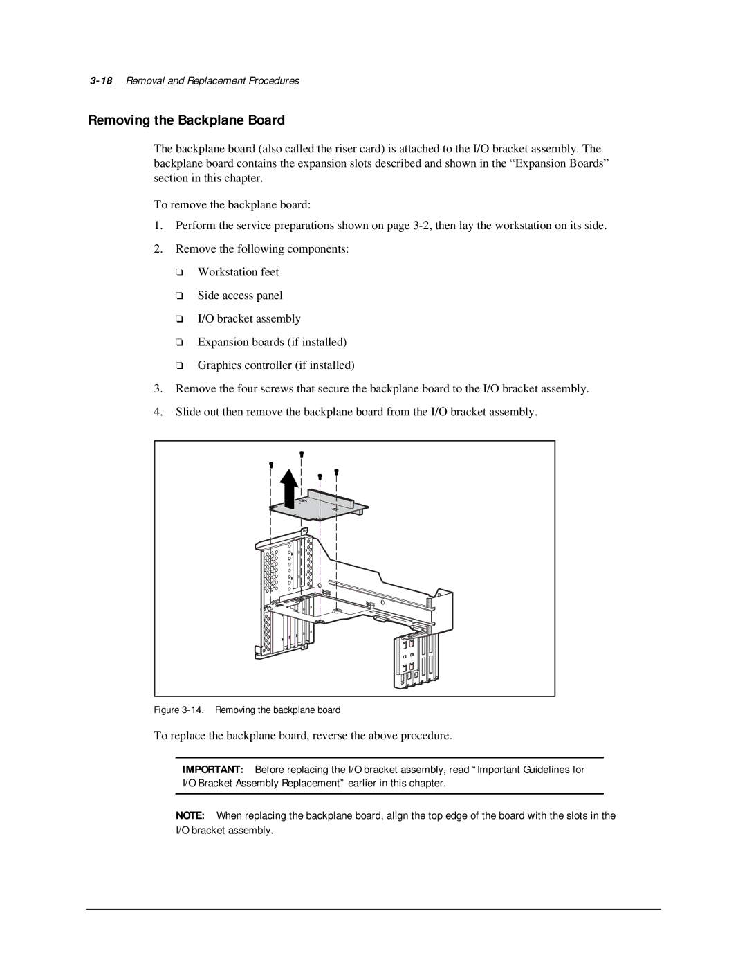
3.Remove the four screws that secure the backplane board to the I/O bracket assembly.
4.Slide out then remove the backplane board from the I/O bracket assembly.
Figure 3-14. Removing the backplane board
To replace the backplane board, reverse the above procedure.
IMPORTANT: Before replacing the I/O bracket assembly, read “Important Guidelines for I/O Bracket Assembly Replacement” earlier in this chapter.
NOTE: When replacing the backplane board, align the top edge of the board with the slots in the I/O bracket assembly.