JET SKI Watercraft
Page
Quick Reference Guide
Page
JET SKI Watercraft
List of Abbreviations
Emission Control Information
Fuel Information
Exhaust Emission Control System
Foreword
Page
Page
General Information
Smart Learning Operation mode SLO JT1500-A2 model ∼
Adjustments
Kawasaki Diagnostic System KDS Software
Before Servicing
Auxiliary Cooling
General Information
Edges of Parts
Battery Ground
Solvent
Arrangement and Cleaning of Removed Parts
Cleaning Watercraft before Disassembly
Replacement Parts
Storage of Removed Parts
Tightening Torque
Assembly Order Tightening Sequence
Force
Gasket, O-ring
Press
Liquid Gasket, Locking Agent
Ball Bearing
Oil Seal, Grease Seal
Electrical Wires
Circlips, Cotter Pins
Lubrication
Direction of Engine Rotation
Model Identification
General Specifications
Engine Oil
Items JT1500-A1 ∼ A2
Electrical Equipment
Units of Force Units of Power
Units of Volume Units of Pressure
Unit Conversion Table Prefixes for Units Units of Length
Units of Mass
Page
Periodic Maintenance
Periodic Maintenance Chart
Fastener Torque Remarks Kgf·m Ft·lb Fuel System
Torque and Locking Agent
Engine Lubrication System
Exhaust System
Fastener Torque Remarks Kgf·m
Engine Top End
Engine Bottom End
Engine Removal/Installation
Cooling and Bilge Systems
Pump and Impeller
Steering
Fastener Torque Remarks Kgf·m Ft·lb
Hull/Engine Hood
Electrical System
Threads dia. mm Torque Kgf·m Ft·lb
General Fasteners stainless bolt and nut
Standard Service Limit Fuel System
Specifications
Special Tools and Sealant
Air Filter Drain Caps Inspection and Cleaning
Periodic Maintenance Procedures Fuel System
Throttle Control System Inspection
Air Filter Inspection and Cleaning
Periodic Maintenance Procedures
Fuel Vent Check Valve Inspection
Engine Lubrication System
Fuel Pump Screen Cleaning
Throttle Shaft Spring Inspection
Engine Oil Change
Dry
Oil Filter Replace
Air Suction Valve Inspection
Periodic Maintenance Procedures Engine Top End
Valve Clearance Inspection
Periodic Maintenance
Inlet Valve Clearance Adjustment Chart
Exhaust Valve Clearance Adjustment Chart
Cooling and Bilge Systems
Engine Bottom End
Engine Mounting Bolts Inspection and Tightness
Coupling Damper Inspection
Periodic Maintenance
Bilge System Flushing
Steering
Periodic Maintenance Procedures Pump and Impeller
Impeller Inspection
Steering Cable/Shift Cable Inspection
Battery Terminals Inspection
Battery Charging Condition Inspection
Hull/Engine Hood
Electrical System
Lubrication
Spark Plug Cleaning and Inspection
Steering Cable Ball Joint a at Steering Shaft
Lubricate the following with a penetrating rust inhibitor B
Hose and Hose Connect Inspection
Nuts, Bolts, and Fasteners Tightness Inspection
Nut, Bolt and Fastener to be checked
JT1500-A2 ∼
Rubber Strap Inspection
Page
Fuel System DFI
Fuel System DFI
Fuel System Diagram
Exploded View
Fastener Torque Remarks Kgf·m Ft·lb
Fuel System DFI
Fastener Torque Remarks Kgf·m
Fuel System DFI
Fastener Torque Remarks Kgf·m Ft·lb
Digital Fuel Injection System
Standard
Fuel System DFI
Special Tools and Sealant
DFI Parts Location
Fuel System DFI
Dummy
DFI System
Part Name
Terminal Names
Terminal Numbers of ECU Connectors
DFI Servicing Precautions
For JT1500-A2 ∼
Silicone Sealant Kawasaki Bond 56019-120 -Seals Connector
Dealer Mode
User Mode
Self-Diagnosis Self-diagnosis Outline
Possible Problems Fail-Safe Function
Self-Diagnosis Service Code Character Table
Displayed on
JT1500-A1
Self-Diagnosis
Memory of Service Code Character
Watercraft conditions when problem occurred
Troubleshooting the DFI System Sample Diagnosis Sheet
Troubleshooting the DFI System
Throttle Sensor Removal/Adjustment
Throttle Sensor Service Code/Character-11/tPS
Input Voltage Inspection
Be sure the battery is fully charged
Input Voltage at ECU Standard 4.75 ∼ 5.25 V DC
Output Voltage Inspection
Resistance Inspection
ECU Joint Connector E Throttle Sensor
Inlet Air Pressure Sensor Installation
Inlet Air Pressure Sensor Service Code/Character-12/bOSt
Inlet Air Pressure Sensor Removal
Input Voltage at Sensor Connector Standard 4.75 ∼ 5.25 V DC
Joint Connector E Inlet Air Pressure Sensor
Inlet Air Temperature Removal/Installation
Inlet Air Temperature Sensor Service Code/Character-13/AIrt
Sensor Resistance Inspection
Fuel System DFI
Water Temperature Sensor Removal/Installation
Water Temperature Sensor Service Code/Character-14/AqUt
Output Voltage at ECU Standard about 3 ∼ 4 V at 20C 68F
ECU Joint Connector E Water Temperature Sensor
Crankshaft Sensor Removal/Installation
Crankshaft Sensor Service Code/Character-21/CrAg
Crankshaft Sensor Inspection
Camshaft Position Sensor Removal/Installation
Camshaft Position Sensor Service Code/Character-23/CAAg
Camshaft Position Sensor Inspection
Vehicle-down Sensor Installation
Vehicle-down Sensor Service Code/Character-31/dOS
Vehicle-down Sensor Removal
Vehicle-down Sensor Inspection
Fuel System DFI
Fuel Injector Removal
Fuel Injector Installation
Audible Inspection
Injector Signal Test
Injector Unit Test
Injector Resistance Inspection
Injector Voltage Inspection
Injector Fuel Line Inspection
ECU
Ignition Coil Removal/Installation
Ignition Coils Service Code/Character-51, 52/COL1, COL2
Fuel System DFI
Possible Causes Action Chapter
Engine Overheating Service Code/Character-71/HEAt
Low Engine Oil Pressure Service Code/Character-72/OILP
Oil Temperature Sensor Removal/Installation
Sensor Resistance Inspection
JT1500-A2 model ∼
Engine Oil Overheating Service Code/Character-76/OILH
ECU Power Supply Inspection
ECU Installation
ECU Removal
ECU connector B in this chapter figure
ECU Power Source Circuit
Relay Assembly Removal
DFI Power Source
Relay Assembly Inspection
Main Fuse Inspection
Fuel Pump Relay
Relay Coil Terminals 6 Relay Switch Terminals 5
Throttle Case Removal/Disassembly
Throttle Cable Adjustment
Throttle Lever, Cable and Case
Free Play Inspection
Throttle Case Assembly/Installation
Throttle Cable Removal
Throttle Cable Installation
Throttle Cable Inspection
Throttle Case and Cable Lubrication
Air Filter
Air Filter Installation
Air Filter Removal
Air Filter Assembly
Air Filter Disassembly
Throttle Body Assy
ISC Idle Speed Controller Inspection
ISC Idle Speed Controller Removal/Installation
ISC a
ISC Resistance Inspection
Inlet Manifold Removal
Inlet Manifold
Inlet Manifold Installation
Fuel System DFI
Fuel Pressure Inspection
Fuel Line
Fuel Flow Rate Inspection
Amount of Fuel Flow Standard 67 mL or more for 3 seconds
Fuel Vent Check Valve Mounting
Fuel Vent Check Valve
Fuel Filter Removal
Fuel Filter
Fuel Filter Installation
Fuel Pump Removal
Fuel Pump
JT1500-A2 ∼ model
Power Source Voltage Inspection
Fuel Pump Installation
Operating Voltage Inspection
Fuel Pump Relay Inspection
Fuel Pump Relay Removal
Fuel Tank Removal
Fuel Tank
Fuel Tank Cleaning
Fuel Tank Installation
Fuel Filler and Tube Removal
Fuel Filler and Tube Installation
Engine Lubrication System
Exploded View
Fastener Torque Remarks Kgf·m Ft·lb
Engine Oil Flow Chart
Passage
Oil Pressure Measurement
Special Tool and Sealant
Oil Level Inspection
Engine Oil and Oil Filter
Preliminary Check
Ordinary standard Check
Oil Filter Replacement
Oil Cooler
Oil Cooler Installation
Oil Cooler Removal
Oil Cooler Assembly
Oil Cooler Disassembly
Oil Cooler Inspection
Breather Case and Oil Separator Tank
Breather Case Installation
Breather Case Removal
Oil Separator Tank Removal
Blowby Gas System Inspection
Oil Separator Tank Installation
Oil Pan
Oil Pan Installation
Oil Pan Removal
Oil Pump Sprocket, Oil Pump and Oil Pressure Relief Valve
Oil Pump Sprocket Installation
Oil Pump Sprocket Removal
Oil Pump Removal
Oil Pump Installation
Oil Pump Inspection
Oil Screen Installation
Oil Screen Removal
Oil Pump Sprocket Chain Removal
Oil Pressure Relief Valve Inspection
Oil Pressure Measurement
Oil Pressure Measurement
Engine Lubrication System
Oil Pressure Switch Removal
Oil Pressure Switch
Oil Pressure Switch Installation
Page
Exhaust System
Exploded View
Fastener Torque Remarks Kgf·m
Exhaust Manifold Removal
Exhaust Manifold
Exhaust Manifold Installation
Exhaust Manifold Cleaning and Inspection
Exhaust Pipe
Exhaust Pipe Installation
Exhaust Pipe Removal
Exhaust Pipe Cleaning and Inspection
Water Box Muffler
Water Box Muffler Installation
Water Box Muffler Removal
Water Box Muffler Inspection
Engine Top End
Exploded View
Fastener
Engine TOP END
Engine TOP END
Fastener Torque Remarks Kgf·m
Cylinder Head
Standard Service Limit Camshafts
Valves
Cylinder, Piston
Standard Service Limit
Special Tools and Sealant
Engine TOP END
Engine TOP END
Air Suction Valve Installation
Clean Air System
Clean Air System Hose Inspection
Air Suction Valve Removal
Cylinder Head Cover
Cylinder Head Cover Installation
Cylinder Head Cover Removal
Camshaft Chain Tensioner
Camshaft Chain Tensioner Installation
Camshaft Chain Tensioner Removal
Camshaft Removal
Camshaft, Camshaft Chain
Camshaft Installation
Piston TDC Finding
Special Tool TDC Measurement Tool
Camshaft Runout
Camshaft, Camshaft Cap Wear
Camshaft Chain Removal
Cylinder Compression Measurement
Cylinder Head
Cylinder Head Removal
Cylinder Head Installation
Cylinder Head Warp
Valves
Valve Installation
Valve Clearance Check
Valve Removal
Valve-to-Guide Clearance Measurement Wobble Method
Valve Guide Installation
Valve Seat Repair
Valve Seat Inspection
Seat Cutter Operation Care
Operating Procedures
Marks Stamped on the Cutter
Engine TOP END
Engine TOP END
Engine TOP END
Cylinder Removal
Cylinder, Pistons
Piston Removal
Oil ring rails have no top or bottom
Piston/Cylinder Installation
With the Special Tools
With the Hand
Piston Wear
Cylinder Wear
Piston Ring, Piston Ring Groove Wear
Piston Ring Groove Width
Piston Ring End Gap
Piston Ring Thickness
Page
Engine Removal/Installation
Exploded View
Fastener Torque Remarks Kgf·m
Engine Removal
Engine Removal/Installation
Engine Damper Removal
Engine Installation
Engine Damper Installation
Engine Bottom End
Exploded View
Fastener Torque Remarks Kgf·m
Connecting Rod Big End Bearing Insert Selection
Standard Service Limit Crankshaft, Connecting Rods
Crankshaft Main Journal Diameter 40.984 ∼ 41.000 mm 40.96 mm
Special Tools and Sealant
Kawasaki Bond Liquid Gasket Black
Coupling/Output Shaft Removal
Coupling
Coupling/Output Shaft Installation
Output Cover Oil Seal Replacement
Oil Seal Inspection
Magneto Cover Bearing Replacement
Ball Bearing Lubrication
Ball Bearing Inspection
Magneto Flywheel
Magneto Flywheel Installation
Magneto Flywheel Removal
InstallMagneto Cover see Coupling/Output Shaft Installation
Stator
Stator Installation
Stator Removal
Crankcase Splitting
Crankcase Splitting
Crankcase Assembly
Following the sequence numbers, tighten the M8 bolts
Crankshaft Installation
Crankshaft and Connecting Rods
Crankshaft Removal
Connecting Rod Installation
Connecting Rod Removal
Engine Bottom END
Be careful not to overtighten the nuts
Connecting Rod Bend
Connecting Rod Big End Side Clearance
Connecting Rod Twist
Connecting Rod Big End Bearing Insert/Crankpin Wear
92139-3709
Crankshaft Main Bearing Insert/Journal Wear
Marking Position
Crankshaft Runout
Crankshaft Side Clearance
Measure the crankshaft runout
Crankshaft
Cooling and Bilge Systems
Exploded View
Fastener Torque Remarks Kgf·m
Breather Cleaning and Inspection
Breather Installation
Bilge System
Breather Removal
Filter Cleaning and Inspection
Filter Installation
Cooling and Bilge System Hoses
Hose Installation
Hose Removal
Hose Inspection
Cooling and Bilge System Flushing
Cooling and Bilge System Flow Diagram
Cooling and Bilge Systems
Water Pipe
Water Pipe Installation
Water Pipe Removal
After Submerging
Summary Procedures after Submerging
Cooling and Bilge Systems
Detailed Procedures after Submerging
Cooling and Bilge Systems
Cooling and Bilge Systems
Page
Drive System
Exploded View
Fastener Torque Remarks Kgf·m
Standard Service Limit Drive Shaft
Specification
Drive System
Drive Shaft Holder Removal/Disassembly
Drive Shaft Removal/Installation
Drive Shaft/Drive Shaft Holder
Drive Shaft Holder Assembly/Installation
Drive Shaft Runout
Pump and Impeller
Exploded View
Fastener Torque Remarks Kgf·m
Standard Service Limit Jet Pump
Pump and Impeller
Pump Removal
Pump Installation
Torque Pump Mounting Bolts 36 N·m 3.7 kgf·m, 27 ft·lb
Pump Disassembly
Special Tool Oil Seal & Bearing Remover 57001-1058 a
JT1500-A1,A2 ∼
Pump Assembly
Special Tool Bearing Driver Set
Pump and Impeller
JT1500-A1, A2 ∼
Impeller Outside Diameter Measurement
Water Filter Cover Removal/Installation
Pump Inspection
Impeller Clearance
Page
Steering
Exploded View
36 ∼
Special Tool and Sealant
Steering Cable
Steering Cable Adjustment
Steering Cable Removal
Special Tool Box Wrench
Steering Cable Inspection
Steering Cable Installation
Steering Cable Lubrication
Handlebar Removal
Handlebar
Handlebar Installation
Steering
Steering Removal
Steering
Steering
Steering Installation
Torque the steering shaft locknut a
Steering
Reverse System
Shift Cable Adjustment
Shift Cable Removal
Steering
Shift Cable Inspection
Shift Cable Installation
Shift Cable Lubrication
Shift Lever Shaft Removal/Installation
Reverse Bucket Removal/Installation
Hull/Engine Hood
Exploded View
Fastener Torque Remarks Kgf·m
HULL/ENGINE Hood
HULL/ENGINE Hood
Fittings
Seat Installation
Seat Removal
Front Storage Compartment Cover Removal
Front Storage Compartment Cover Disassembly
Front Storage Compartment Cover Assembly
Mirror Removal
Mirror Installation
Mirror Stay Removal
Mirror Stay Installation
Storage Pocket Disassembly/Assembly
Front Storage Pocket Installation
Front Storage Pocket Removal
Crossmember Removal
Crossmember Installation
Drain Plug Housing Removal
Handrail Installation
Drain Plug Housing Installation
Exhaust Outlet Installation
Reboarding Step Installation
Stabilizer Installation
Stabilizer Removal
Reboarding Step Removal
Hull Replacement
Rubber Parts Location
Rubber Parts
HULL/ENGINE Hood
Front Bumper Installation
Rivet Installation
Rear Bumper Installation
Rivet Removal
Side Bumper Removal
Side Bumper Installation
Page
Electrical System
Electrical System
Parts Location
Electrical System
Electrical System
Exploded View
30 ∼ 40 in·lb Starter Cable Mounting Nuts
Electrical System
Fastener Torque Remarks Kgf·m
Electrical System
Electrical System
Wiring Diagram
Electrical System
JT1500-A2 ∼
Electrical System
Electric Starter System
Standard Service Limit Battery
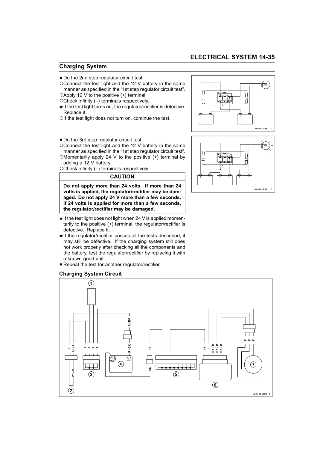
Charging System
Ignition System
Electrical System
Precautions
Electrical Connectors Female Connectors a Male Connectors B
Wiring Inspection
Electrical Wiring
Installation
Battery
Removal
Electrolyte Filling
Electrical System
Initial Charge
Precautions
Charging Condition Inspection
Interchange
Refreshing Charge
Electrical System
Electric Starter System
Starter Relay Installation
Starter Relay Removal
Starter Relay Inspection
Starter Motor Removal
Starter Motor Installation
Starter Motor Assembly
Starter Motor Disassembly
Brush Inspection
Commutator Cleaning and Inspection
Brush Lead Inspection
Armature Inspection
Brush Plate and Terminal Bolt Inspection
Reduction Gear Inspection
Reduction Gear Removal/Installation
Electrical System
Charging System
Regulator/Rectifier Removal/Installation
Magneto Output Voltage
Regulator Inspection
Regulator/Rectifier Inspection
Charging System Circuit
Electrical System
Ignition System
Crankshaft Sensor Installation
Crankshaft Sensor Removal
Timing Rotor Removal
Timing Rotor Installation
Ignition Coil Removal
Ignition Coil Installation
Measuring arcing distance
Ignition Coil Inspection
Measuring coil resistance
Camshaft Position Sensor Removal
Camshaft Position Sensor Installation
Measuring spark plug lead resistance
Igniter Inspection
Igniter Removal/Installation
Ignition Coil Primary Peak Voltage Standard 250 V or more
Camshaft Position Sensor Peak Voltage Inspection
Crankshaft Sensor Peak Voltage Check
Spark Plug Adjustment
Spark Plug Installation
Spark Plug Cleaning
Spark Plug Removal
Ignition System Circuit
Electrical System
Kawasaki Smart Steering System
Steering Position Sensor and Magnet Installation
Steering Position Sensor and Magnet Removal
Steering Position Sensor Clearance
Inspection of Kawasaki Smart Steering System
Steering Position Sensor Input Voltage Inspection
Steering Position Sensor Output Voltage Inspection
Steering Position Sensor Circuit
Sensors
Speed Sensor Removal/Installation
Speed Sensor Inspection
Fuel Level Sensor Inspection
Throttle Sensor Removal/Installation
Inlet Air Temperature Sensor Inspection
Water Temperature Sensor Inspection
Oil Temperature Sensor Inspection
Throttle Sensor Inspection
Display Function Inspection
Multifunction Meter
MODE/SET Button Inspection
Speedometer Inspection
Speed Sensor Electric Source Inspection
Tachometer Inspection
Battery Symbol/bAt Characters/LED Inspection
Buzzer Inspection
Electrical System
Circuit Inspection
Relay Assembly
Relay Assembly Circuit Inspection with the battery connected
Switch Inspection
Switches
Fuse
Page
Storage
Cooling System
Preparation for Storage
Bilge System
Engine Oil
Engine
Do not allow any soda solution to enter the battery
Battery
Air Filter
Engine Mounting Bolts
General
General Inspection
Removal from Storage
Test Run
Page
Appendix
Cable, Wire and Hose Routing
Appendix
Appendix
Appendix
Appendix
Appendix
Appendix
Appendix
Appendix
Appendix
Appendix
Appendix
Appendix
Appendix
Appendix
Appendix
Appendix
Appendix
Appendix
Appendix
Appendix
Appendix
Appendix
Appendix
Appendix
Appendix
Appendix
Appendix
Appendix
Appendix
Engine Doesn’t Start, Starting Difficulty
Troubleshooting Guide
Poor Running at Low Speed
Poor Running or No Power at High Speed
Over Cooling
Overheating
Abnormal Engine Noise
Oil Pressure Warning Light Goes On
Battery Trouble
Engine Activates Slow Down Mode
Poor Performance through Engine
Runs Properly
Model Application