Return to Section TOC
Return to Section TOC
Return to Master TOC
Return to Master TOC
TROUBLESHOOTING & REPAIR
DYNAMIC CAPACITOR BALANCE TEST (continued)
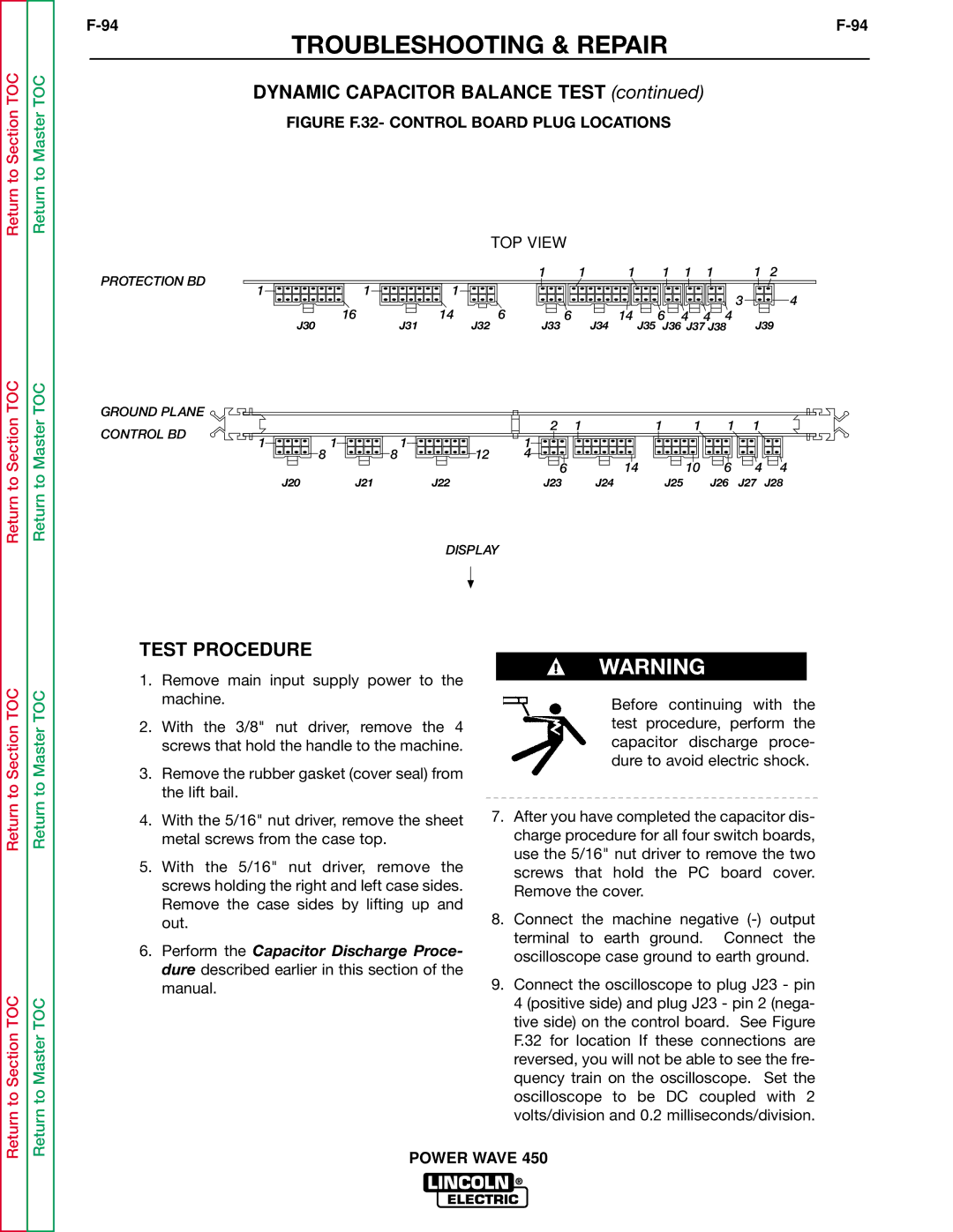
FIGURE F.32- CONTROL BOARD PLUG LOCATIONS
|
|
|
| TOP VIEW |
|
|
|
|
|
|
| |
PROTECTION BD |
|
|
| 1 | 1 | 1 | 1 | 1 | 1 |
| 1 | 2 |
1 | 1 |
|
|
|
|
|
|
|
|
|
| |
1 |
|
|
|
|
|
|
| 3 |
| 4 | ||
| 16 | 14 |
| 6 |
|
|
|
|
|
| ||
| J32 | 6 | 14 | 6 | 4 | 4 | 4 | J39 | ||||
| J30 | J31 | J33 | J34 | J35 | J36 J37 J38 | ||||||
GROUND PLANE |
|
|
| 2 | 1 | 1 | 1 | 1 | 1 |
|
CONTROL BD |
|
|
|
| ||||||
1 | 1 |
| 1 |
|
|
|
|
|
| |
1 | 12 |
|
|
|
|
|
| |||
| 8 | 8 | 4 |
| 14 | 10 | 6 | 4 | 4 | |
|
|
|
| 6 |
| |||||
J20 | J21 | J22 |
| J23 | J24 | J25 |
| J26 | J27 | J28 |
DISPLAY
Return to Section TOC
Return to Section TOC
Return to Master TOC
Return to Master TOC
TEST PROCEDURE
1.Remove main input supply power to the machine.
2.With the 3/8" nut driver, remove the 4 screws that hold the handle to the machine.
3.Remove the rubber gasket (cover seal) from the lift bail.
4.With the 5/16" nut driver, remove the sheet metal screws from the case top.
5.With the 5/16" nut driver, remove the screws holding the right and left case sides. Remove the case sides by lifting up and out.
6.Perform the Capacitor Discharge Proce- dure described earlier in this section of the manual.
WARNING
Before continuing with the test procedure, perform the capacitor discharge proce- dure to avoid electric shock.
7.After you have completed the capacitor dis- charge procedure for all four switch boards, use the 5/16" nut driver to remove the two screws that hold the PC board cover. Remove the cover.
8.Connect the machine negative
9.Connect the oscilloscope to plug J23 - pin 4 (positive side) and plug J23 - pin 2 (nega- tive side) on the control board. See Figure F.32 for location If these connections are reversed, you will not be able to see the fre- quency train on the oscilloscope. Set the oscilloscope to be DC coupled with 2 volts/division and 0.2 milliseconds/division.