Return to Section TOC
Return to Section TOC
Return to Master TOC
Return to Master TOC
TROUBLESHOOTING & REPAIR
AUXILIARY TRANSFORMER TEST #1 (continued)
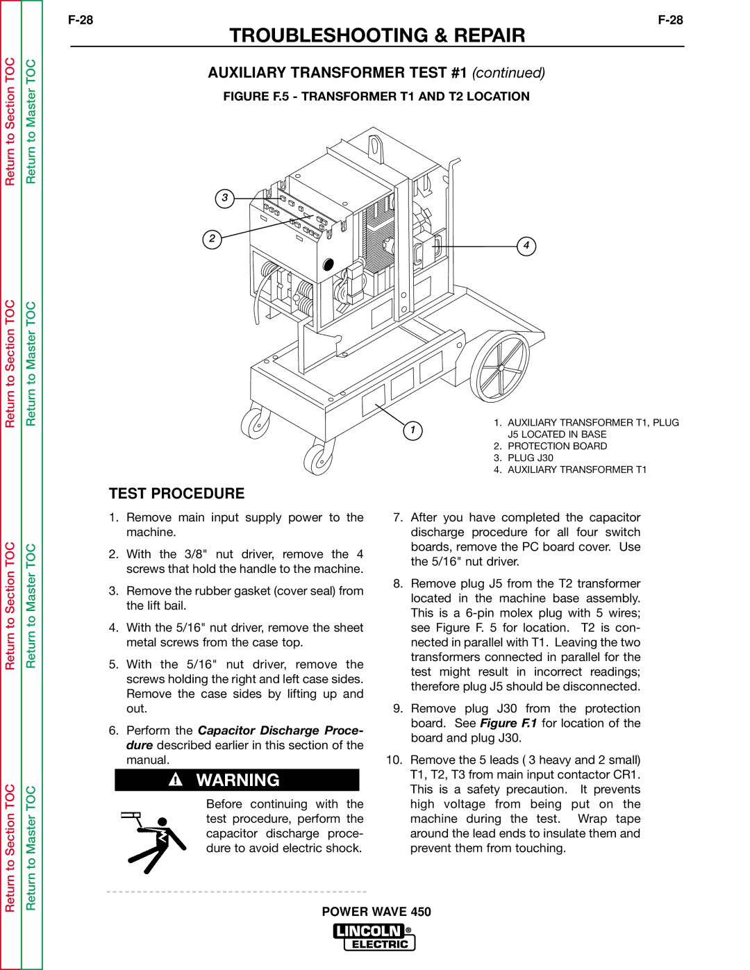
FIGURE F.5 - TRANSFORMER T1 AND T2 LOCATION
3
2 ![]()
![]()
![]()
![]() 4
4
1. | AUXILIARY TRANSFORMER T1, PLUG |
1 | J5 LOCATED IN BASE |
| |
2. | PROTECTION BOARD |
3. | PLUG J30 |
4. | AUXILIARY TRANSFORMER T1 |
TEST PROCEDURE
Return to Section TOC
Return to Section TOC
Return to Master TOC
Return to Master TOC
1.Remove main input supply power to the machine.
2.With the 3/8" nut driver, remove the 4 screws that hold the handle to the machine.
3.Remove the rubber gasket (cover seal) from the lift bail.
4.With the 5/16" nut driver, remove the sheet metal screws from the case top.
5.With the 5/16" nut driver, remove the screws holding the right and left case sides. Remove the case sides by lifting up and out.
6.Perform the Capacitor Discharge Proce- dure described earlier in this section of the manual.
WARNING
Before continuing with the test procedure, perform the capacitor discharge proce- dure to avoid electric shock.
7.After you have completed the capacitor discharge procedure for all four switch boards, remove the PC board cover. Use the 5/16" nut driver.
8.Remove plug J5 from the T2 transformer located in the machine base assembly. This is a
9.Remove plug J30 from the protection board. See Figure F.1 for location of the board and plug J30.
10.Remove the 5 leads ( 3 heavy and 2 small) T1, T2, T3 from main input contactor CR1. This is a safety precaution. It prevents high voltage from being put on the machine during the test. Wrap tape around the lead ends to insulate them and prevent them from touching.