Return to Section TOC
Return to Master TOC
TROUBLESHOOTING & REPAIR
PIEZO-ELECTRIC ALARM BUZZER TEST
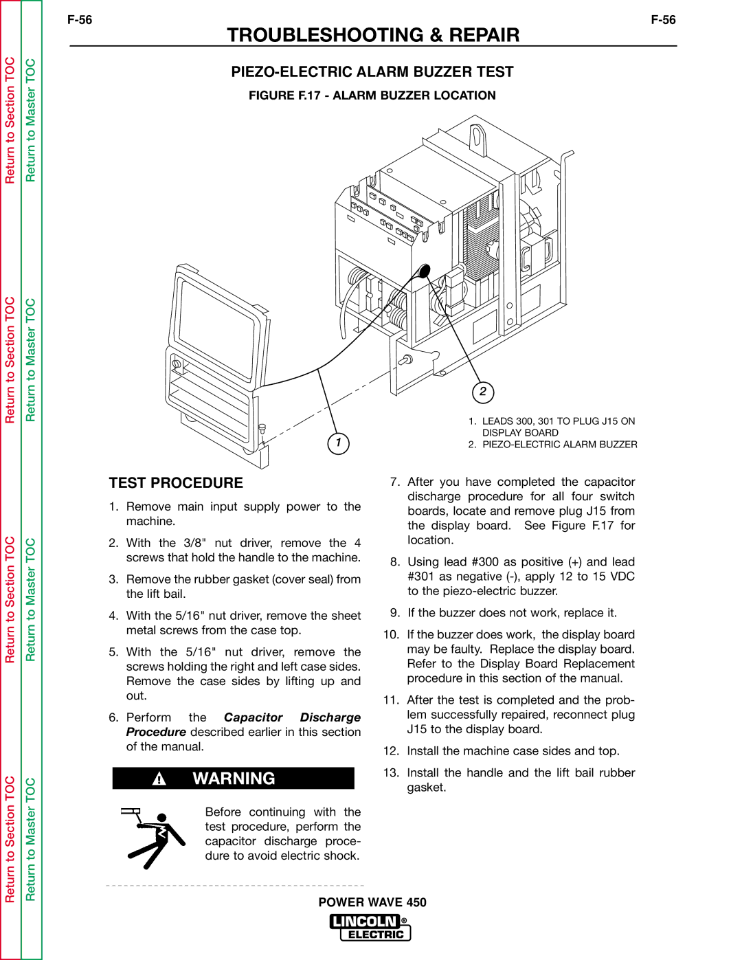
FIGURE F.17 - ALARM BUZZER LOCATION
Return to Section TOC
Return to Section TOC
Return to Section TOC
Return to Master TOC
Return to Master TOC
Return to Master TOC
1
TEST PROCEDURE
1.Remove main input supply power to the machine.
2.With the 3/8" nut driver, remove the 4 screws that hold the handle to the machine.
3.Remove the rubber gasket (cover seal) from the lift bail.
4.With the 5/16" nut driver, remove the sheet metal screws from the case top.
5.With the 5/16" nut driver, remove the screws holding the right and left case sides. Remove the case sides by lifting up and out.
6.Perform the Capacitor Discharge Procedure described earlier in this section of the manual.
WARNING
Before continuing with the test procedure, perform the capacitor discharge proce- dure to avoid electric shock.
2
1.LEADS 300, 301 TO PLUG J15 ON DISPLAY BOARD
2.
7.After you have completed the capacitor discharge procedure for all four switch boards, locate and remove plug J15 from the display board. See Figure F.17 for location.
8.Using lead #300 as positive (+) and lead #301 as negative
9.If the buzzer does not work, replace it.
10.If the buzzer does work, the display board may be faulty. Replace the display board. Refer to the Display Board Replacement procedure in this section of the manual.
11.After the test is completed and the prob- lem successfully repaired, reconnect plug J15 to the display board.
12.Install the machine case sides and top.
13.Install the handle and the lift bail rubber gasket.