Return to Section TOC
Return to Section TOC
Return to Master TOC
Return to Master TOC
TROUBLESHOOTING & REPAIR
FAN MOTOR REMOVAL AND REPLACEMENT (continued)
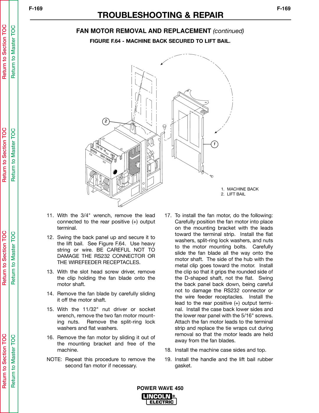
FIGURE F.64 - MACHINE BACK SECURED TO LIFT BAIL.
2
1
1. MACHINE BACK
2. LIFT BAIL
Return to Section TOC
Return to Section TOC
Return to Master TOC
Return to Master TOC
11.With the 3/4" wrench, remove the lead connected to the rear positive (+) output terminal.
12.Swing the back panel up and secure it to the lift bail. See Figure F.64. Use heavy string or wire. BE CAREFUL NOT TO DAMAGE THE RS232 CONNECTOR OR THE WIREFEEDER RECEPTACLES.
13.With the slot head screw driver, remove the clip holding the fan blade onto the motor shaft.
14.Remove the fan blade by carefully sliding it off the motor shaft.
15.With the 11/32" nut driver or socket wrench, remove the two fan motor mount- ing nuts. Remove the
16.Remove the fan motor by sliding it out of the mounting bracket and free of the machine.
NOTE: Repeat this procedure to remove the
second fan motor if necessary.
17.To install the fan motor, do the following: Carefully position the fan motor into place on the mounting bracket with the leads toward the terminal strip. Install the flat washers,
18.Install the machine case sides and top.
19.Install the handle and the lift bail rubber gasket.
