Master TOC
TROUBLESHOOTING & REPAIR
FOR REPLACEMENT OF SWITCH ASSEMBLY
ARC START FOR PW450 ROBOTIC
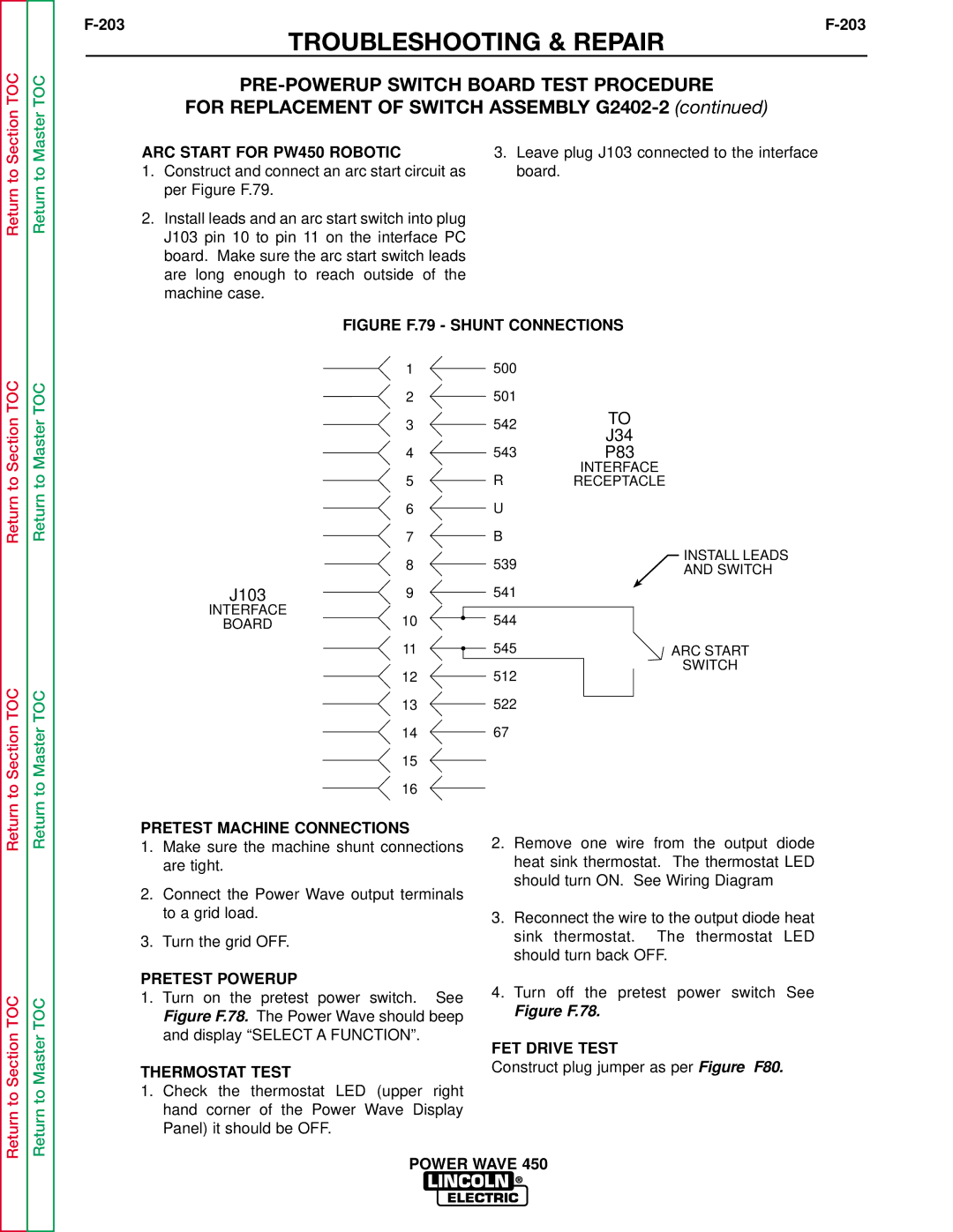
1.Construct and connect an arc start circuit as per Figure F.79.
2.Install leads and an arc start switch into plug J103 pin 10 to pin 11 on the interface PC board. Make sure the arc start switch leads are long enough to reach outside of the machine case.
3.Leave plug J103 connected to the interface board.
Return to Section TOC
to Section TOC
Return to Master TOC
to Master TOC
FIGURE F.79 - SHUNT CONNECTIONS
1500
2501
3 | 542 | TO | |
J34 | |||
|
| ||
4 | 543 | P83 | |
5 | R | INTERFACE | |
RECEPTACLE |
6U
7B
8 | 539 | INSTALL LEADS | |
AND SWITCH | |||
|
|
J103 | 9 | 541 |
|
INTERFACE | 10 | 544 |
|
BOARD |
| ||
| 11 | 545 | ARC START |
|
|
| SWITCH |
12512
13522
1467
Return
Return to Section TOC
Return
Return to Master TOC
PRETEST MACHINE CONNECTIONS
1.Make sure the machine shunt connections are tight.
2.Connect the Power Wave output terminals to a grid load.
3.Turn the grid OFF.
PRETEST POWERUP
1.Turn on the pretest power switch. See Figure F.78. The Power Wave should beep and display “SELECT A FUNCTION”.
THERMOSTAT TEST
1.Check the thermostat LED (upper right hand corner of the Power Wave Display Panel) it should be OFF.
2.Remove one wire from the output diode heat sink thermostat. The thermostat LED should turn ON. See Wiring Diagram
3.Reconnect the wire to the output diode heat sink thermostat. The thermostat LED should turn back OFF.
4.Turn off the pretest power switch See
Figure F.78.
FET DRIVE TEST
Construct plug jumper as per Figure F80.