TOC
TOC
ELECTRICAL DIAGRAMS | ||
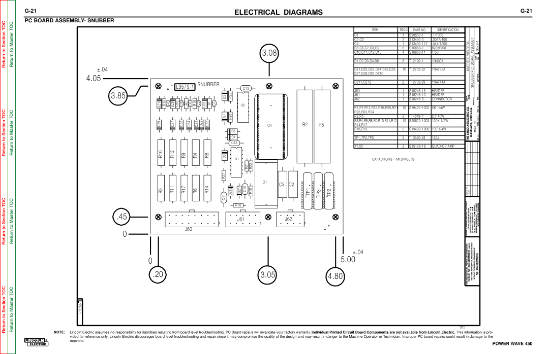
PC BOARD ASSEMBLY- SNUBBER |
|
|
±.04
4.05
3.85
L9579-1 SNUBBER
DZ10 R13 C9 DZ8 R16 C8 R7 C6 R15 C5 | DZ6 R1 C7 |
DZ9 | DZ7 | DZ3 | DZ4 | DZ1 DZ2 | DZ5 |
C13
|
|
| R23 |
|
|
|
| ||
D2 |
|
| |||||||
|
|
|
|
|
|
|
|
| X2 |
|
|
|
|
|
|
|
|
| |
|
|
| |||||||
|
|
|
|
|
|
|
|
|
|
|
|
|
|
|
|
|
|
|
|
D1 |
| R24 |
| ||||||
|
| ||||||||
|
|
|
|
|
|
|
|
|
|
|
|
|
|
|
|
|
|
|
|
|
|
|
|
|
|
|
|
|
|
|
|
|
|
| D5 |
|
| ||
|
|
| |||||||
3.08
C4
|
| ITEM | REQ’D | PART NO. | IDENTIFICATION |
|
|
|
|
|
|
|
|
| C1 | 1 | .1/1000 |
|
| P.C. BOARD ASSEMBLY |
|
|
|
| |
|
| C2,C3 | 2 | .0047/400 | INVERTER WELDERS | NO.SHT. L |
| |||||
|
| C4 | 1 | .047/1200 |
| |||||||
|
| C5,C6,C7,C8,C9 | 5 | 820pF/50 |
| |||||||
|
| C10,C11,C12,C13 | 4 |
| ||||||||
|
|
|
|
|
|
| ||||||
|
| D1,D2,D3,D4,D5 | 5 | 1N4004 |
| |||||||
|
|
| ||||||||||
|
|
|
|
|
|
| ||||||
|
| DZ1,DZ2,DZ3,DZ4,DZ5,DZ6 | 10 | 1N4733A |
| |||||||
|
| DZ7,DZ8,DZ9,DZ10 |
|
|
|
| ||||||
|
|
|
|
|
|
| SNUBBER |
|
|
|
| |
|
|
|
|
|
|
|
|
| SUP’S’D’G | |||
|
|
|
|
|
|
|
|
|
| |||
|
| DZ11,DZ12 | 2 | 1N4744A |
|
|
|
| ||||
|
|
|
|
|
|
|
|
|
|
|
| |
|
|
|
|
|
|
|
|
|
|
|
|
|
|
| J60 | 1 | HEADER |
|
|
|
|
|
|
| |
|
| J61 | 1 | HEADER | EQUIP. | TYPE |
|
|
|
|
| |
|
|
|
|
|
| SUBJECT |
|
| REF. | |||
|
| J62 | 1 | CONNECTOR |
|
| ||||||
|
|
|
|
|
|
|
|
|
| DB |
| |
|
| R1,R7,R13,R15,R16,R20,R21 | 10 | LINCOLNELECTRIC CO. | CLEVELAND,OHIO U.S.A. |
|
|
| ||||
|
|
|
| CHK | ||||||||
|
| R22,R23,R24 |
|
|
|
|
| |||||
|
| R2,R5 | 2 | 2.7 10W |
|
|
| |||||
R2 | R5 | R3,R4,R6,R8,R9,R10,R11,R12 | 10 | 100K 1/2W | SCALE FULL |
|
| |||||
R14,R17 |
|
|
|
| DATE | |||||||
|
| R18,R19 | 2 | 100 1/4W |
| |||||||
|
|
|
|
|
|
|
|
| ||||
Return to
TOC
Return to
TOC
R10 | R12 | R9 | R4 | R8 |
R3 | R11 | R17 | R6 | R14 |
D4
C12
|
|
|
|
|
|
|
|
|
|
| |
|
|
|
|
|
|
|
|
|
|
| |
D3 |
| X1 |
|
|
|
|
| ||||
|
|
|
|
|
|
|
|
|
| ||
|
|
|
|
|
|
| R21 | R20 | |||
|
|
|
|
|
|
| |||||
R22 |
|
| DZ11 |
|
|
|
|
| |||
DZ12 | C10 | R19 | |||||||||
|
| ||||||||||
|
|
|
| ||||||||
C11 | |||||||||||
|
|
|
|
| R18 |
|
|
|
|
| |
C1 | C3 | C2 |
|
| TP1,TP2,TP3 | 3 | 160J | THE |
|
| JLV | |
|
|
| DR | |||||
|
|
|
|
|
|
| ||
| X1,X2 | 2 |
|
|
|
| ||
| CAPACITORS = MFD/VOLTS |
|
|
|
|
| ||
xxxxxxxxxxxxxxxx TP1 xxxxxxxxxxxxxxxx | TP3 xxxxxxxxxxxxxxxx TP2 xxxxxxxxxxxxxxxx |
|
|
|
|
|
| |
|
|
| TOLERANCE Ch’geNo.Sht. . E2056 .02 .002 | ADEGREE | AGREE | STANDARDS. | ||
|
|
| t | |||||
|
|
| ")TO | |||||
Return to Section
Return to Section TOC
Return to Master
Return to Master TOC
.45
0
J61
J60
0
.20
J62
3.05
|
|
|
| UNLESSOTHERWISE SPECIFIED | ON HOLE SIZES PER ON 2 PLACE DECIMALS IS ON 3 PLACE DECIMALS IS | ON ALL ANGLES IS .5 OF | MATERIAL TOLERANCE (" WITH PUBLISHED |
|
|
| ±.04 | THIS SHEET CONTAINS PROPRIETARY INFORMATION | OWNED BY THE LINCOLN ELECTRIC CO. AND IS NOT TO BE REPRODUCED, DISCLOSED OR USED | WITHOUT THE EXPRESS PERMISSION OF | THE LINCOLN ELECTRIC CO. |
|
| ||||||
| 5.00 | ||||||
|
|
|
| ||||
4.80 |
|
| |||||
|
|
|
| ||||
CAD
NOTE: Lincoln Electric assumes no responsibility for liablilities resulting from board level troubleshooting. PC Board repairs will invalidate your factory warranty. Individual Printed Circuit Board Components are not available from Lincoln Electric. This information is pro- vided for reference only. Lincoln Electric discourages board level troubleshooting and repair since it may compromise the quality of the design and may result in danger to the Machine Operator or Technician. Improper PC board repairs could result in damage to the machine.
