Return to Section TOC
Return to Section TOC
Return to Master TOC
Return to Master TOC
TROUBLESHOOTING & REPAIR
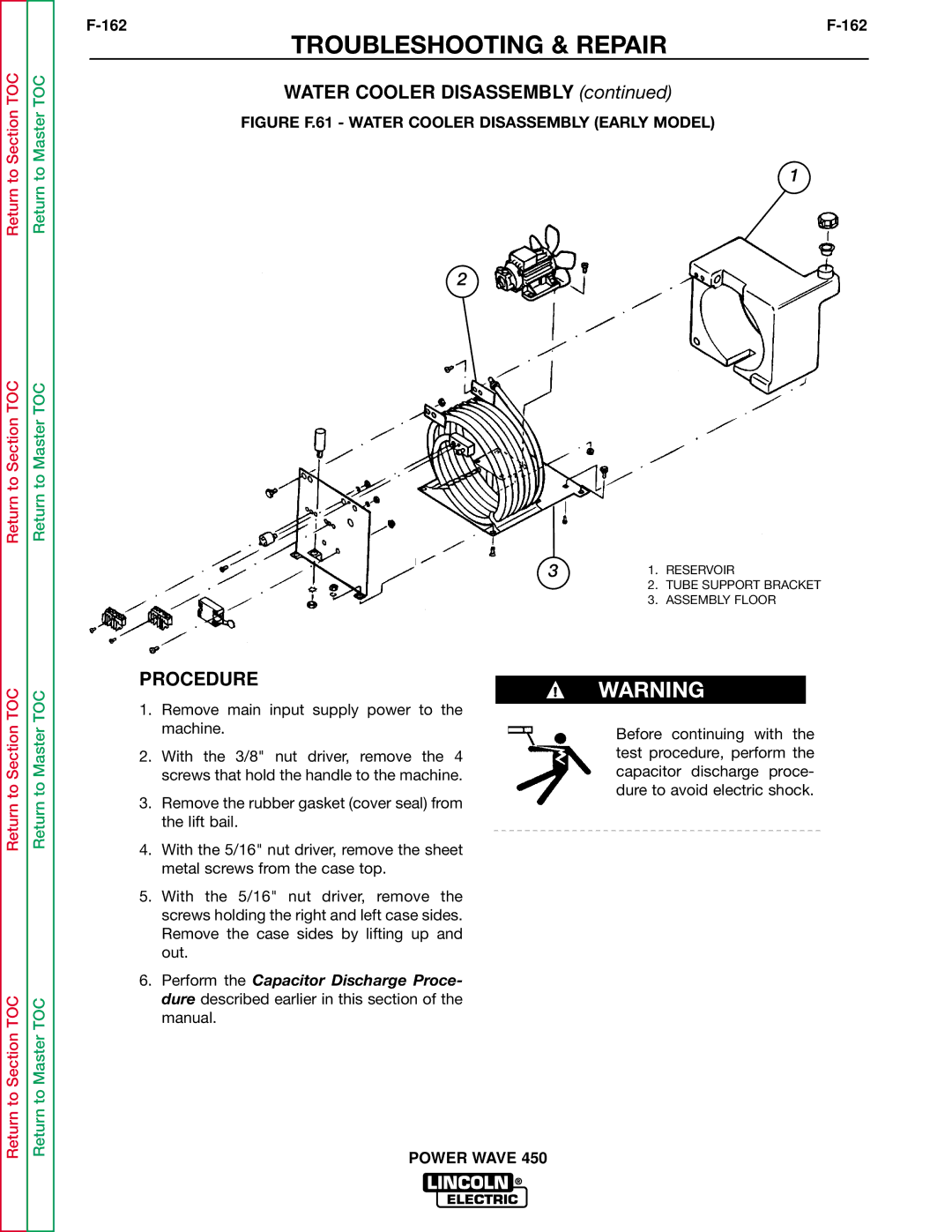
WATER COOLER DISASSEMBLY (continued)
FIGURE F.61 - WATER COOLER DISASSEMBLY (EARLY MODEL)
1
2
3 | 1. | RESERVOIR |
| 2. | TUBE SUPPORT BRACKET |
| 3. | ASSEMBLY FLOOR |
PROCEDURE
WARNING
Return to Section TOC
Return to Section TOC
Return to Master TOC
Return to Master TOC
1.Remove main input supply power to the machine.
2.With the 3/8" nut driver, remove the 4 screws that hold the handle to the machine.
3.Remove the rubber gasket (cover seal) from the lift bail.
4.With the 5/16" nut driver, remove the sheet metal screws from the case top.
5.With the 5/16" nut driver, remove the screws holding the right and left case sides. Remove the case sides by lifting up and out.
6.Perform the Capacitor Discharge Proce- dure described earlier in this section of the manual.
Before continuing with the test procedure, perform the capacitor discharge proce- dure to avoid electric shock.
