Return to Section TOC
Return to Section TOC
Return to Master TOC
Return to Master TOC
TROUBLESHOOTING & REPAIR
FET MODULE REMOVAL AND REPLACEMENT (continued)
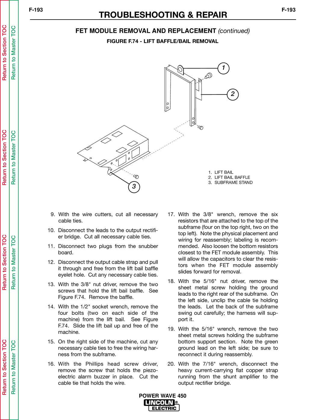
FIGURE F.74 - LIFT BAFFLE/BAIL REMOVAL
1
2
1. | LIFT BAIL |
2. | LIFT BAIL BAFFLE |
3. | SUBFRAME STAND |
3 |
|
Return to Section TOC
Return to Section TOC
Return to Master TOC
Return to Master TOC
9.With the wire cutters, cut all necessary cable ties.
10.Disconnect the leads to the output rectifi- er bridge. Cut all necessary cable ties.
11.Disconnect two plugs from the snubber board.
12.Disconnect the output cable strap and pull it through and free from the lift bail baffle eyelet hole. Cut any necessary cable ties.
13.With the 3/8" nut driver, remove the two screws that hold the lift bail baffle. See Figure F.74. Remove the baffle.
14.With the 1/2" socket wrench, remove the four bolts (two on each side of the machine) from the lift bail. See Figure F.74. Slide the lift bail up and free of the machine.
15.On the right side of the machine, cut any necessary cable ties to free the wiring har- ness from the subframe.
16.With the Phillips head screw driver, remove the screw that holds the piezo- electric alarm buzzer in place. Cut the cable tie that holds the wire.
17.With the 3/8" wrench, remove the six resistors that are attached to the top of the subframe (four on the top right, two on the top left). Note the physical placement and wiring for reassembly; labeling is recom- mended. Also loosen the bottom resistors closest to the FET module assembly. This will allow the capacitors to clear the resis- tors when the FET module assembly slides forward for removal.
18.With the 5/16" nut driver, remove the sheet metal screw holding the ground leads to the right rear of the subframe. On the left side, unclip the cable tie holding the leads. Let the back of the subframe swing out carefully; the harness will sup- port it.
19.With the 5/16" wrench, remove the two sheet metal screws holding the subframe bottom support section. Note the green ground lead on the left side; be sure to reconnect it during reassembly.
20.With the 7/16" wrench, disconnect the heavy
