Return to Section TOC
Return to Section TOC
Return to Master TOC
Return to Master TOC
TROUBLESHOOTING & REPAIR
OUTPUT RECTIFIER DIODES TEST
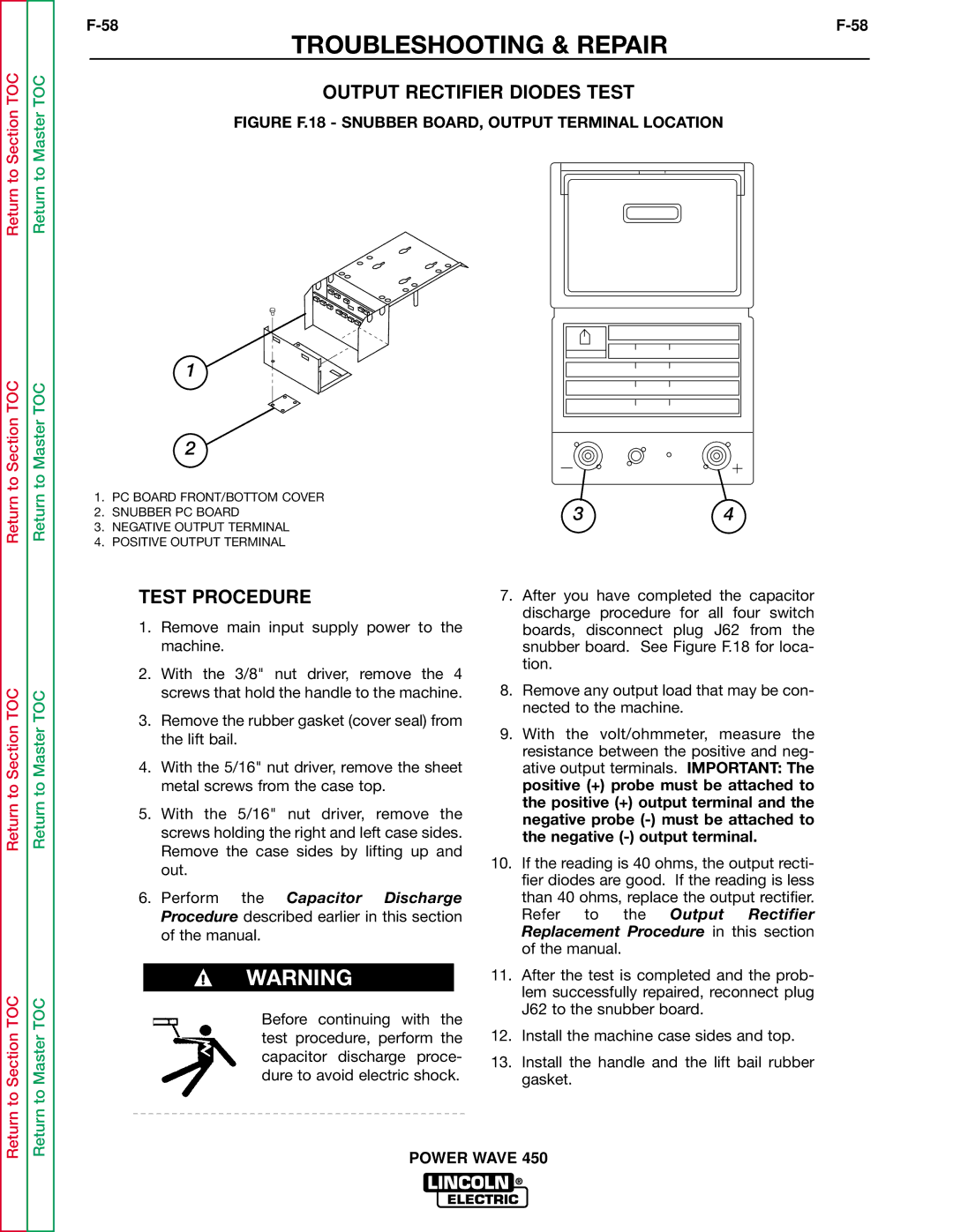
FIGURE F.18 - SNUBBER BOARD, OUTPUT TERMINAL LOCATION
1
| 2 |
|
| |
1. | PC BOARD FRONT/BOTTOM COVER | 3 | 4 | |
2. | SNUBBER PC BOARD | |||
|
| |||
3. | NEGATIVE OUTPUT TERMINAL |
|
| |
4. | POSITIVE OUTPUT TERMINAL |
|
|
Return to Section TOC
Return to Section TOC
Return to Master TOC
Return to Master TOC
TEST PROCEDURE
1.Remove main input supply power to the machine.
2.With the 3/8" nut driver, remove the 4 screws that hold the handle to the machine.
3.Remove the rubber gasket (cover seal) from the lift bail.
4.With the 5/16" nut driver, remove the sheet metal screws from the case top.
5.With the 5/16" nut driver, remove the screws holding the right and left case sides. Remove the case sides by lifting up and out.
6.Perform the Capacitor Discharge Procedure described earlier in this section of the manual.
WARNING
Before continuing with the test procedure, perform the capacitor discharge proce- dure to avoid electric shock.
7.After you have completed the capacitor discharge procedure for all four switch boards, disconnect plug J62 from the snubber board. See Figure F.18 for loca- tion.
8.Remove any output load that may be con- nected to the machine.
9.With the volt/ohmmeter, measure the resistance between the positive and neg- ative output terminals. IMPORTANT: The positive (+) probe must be attached to the positive (+) output terminal and the negative probe
10.If the reading is 40 ohms, the output recti- fier diodes are good. If the reading is less than 40 ohms, replace the output rectifier. Refer to the Output Rectifier Replacement Procedure in this section of the manual.
11.After the test is completed and the prob- lem successfully repaired, reconnect plug J62 to the snubber board.
12.Install the machine case sides and top.
13.Install the handle and the lift bail rubber gasket.