to Section TOC
to Master TOC
THEORY OF OPERATION
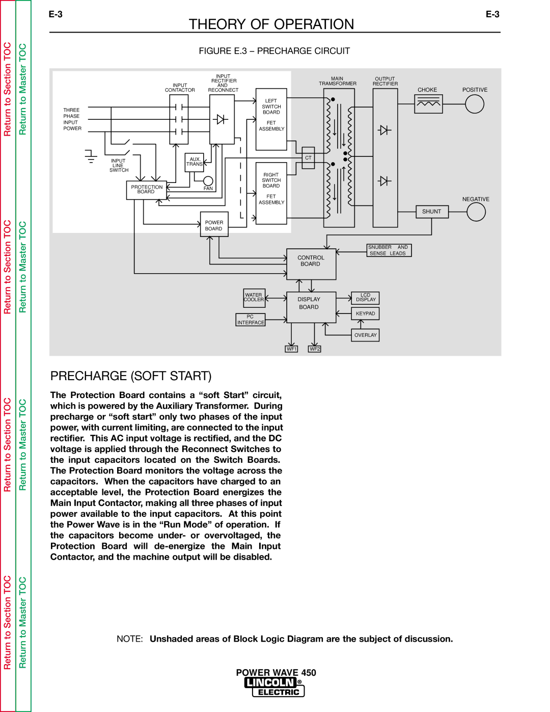
FIGURE E.3 – PRECHARGE CIRCUIT
| INPUT | MAIN | OUTPUT |
|
| RECTIFIER |
| ||
| TRAMSFORMER | RECTIFIER |
| |
INPUT | AND | POSITIVE | ||
CONTACTOR | RECONNECT |
| CHOKE | |
|
| LEFT |
|
|
THREE |
| SWITCH |
|
|
| BOARD |
|
| |
PHASE |
|
|
| |
|
|
|
|
Return
Return to Section TOC
Return
Return to Master TOC
INPUT |
| FET |
POWER |
| ASSEMBLY |
INPUT | AUX. | CT |
TRANS |
| |
LINE |
| |
SWITCH |
| RIGHT |
|
| |
|
| SWITCH |
PROTECTION | FAN | BOARD |
BOARD |
| FET |
|
| |
|
| ASSEMBLY |
| POWER |
|
| BOARD |
|
CONTROL
BOARD
WATER
COOLERDISPLAY
BOARD
PC
INTERFACE
NEGATIVE
SHUNT
SNUBBER AND
SENSE LEADS
LCD
DISPLAY
KEYPAD
Return to Section TOC
Return to Section TOC
Return to Master TOC
Return to Master TOC
OVERLAY
WF1 WF2
PRECHARGE (SOFT START)
The Protection Board contains a “soft Start” circuit, which is powered by the Auxiliary Transformer. During precharge or “soft start” only two phases of the input power, with current limiting, are connected to the input rectifier. This AC input voltage is rectified, and the DC voltage is applied through the Reconnect Switches to the input capacitors located on the Switch Boards. The Protection Board monitors the voltage across the capacitors. When the capacitors have charged to an acceptable level, the Protection Board energizes the Main Input Contactor, making all three phases of input power available to the input capacitors. At this point the Power Wave is in the “Run Mode” of operation. If the capacitors become under- or overvoltaged, the Protection Board will
NOTE: Unshaded areas of Block Logic Diagram are the subject of discussion.