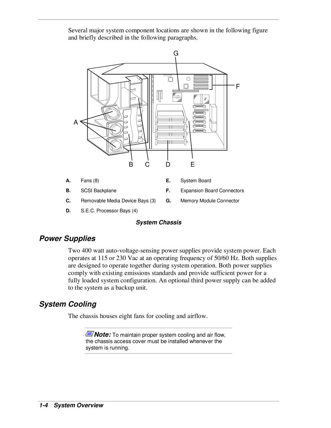
Several major system component locations are shown in the following figure and briefly described in the following paragraphs.
|
|
| G |
|
|
| F |
A |
|
|
|
B | C | D | E |
A. | Fans (8) | E. | System Board |
B. | SCSI Backplane | F. | Expansion Board Connectors |
C. | Removable Media Device Bays (3) | G. | Memory Module Connector |
D.S.E.C. Processor Bays (4)
System Chassis
Power Supplies
Two 400 watt
System Cooling
The chassis houses eight fans for cooling and airflow.
![]() Note: To maintain proper system cooling and air flow, the chassis access cover must be installed whenever the system is running.
Note: To maintain proper system cooling and air flow, the chassis access cover must be installed whenever the system is running.