Rear View
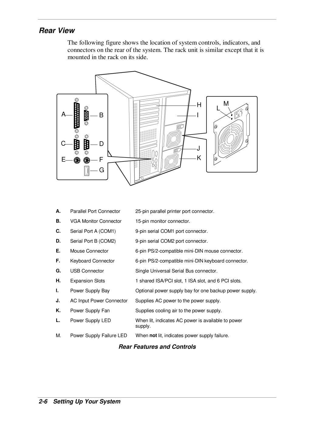
The following figure shows the location of system controls, indicators, and connectors on the rear of the system. The rack unit is similar except that it is mounted in the rack on its side.
|
| H | M |
A | B | I | L |
| |||
C | D | J |
|
|
|
| |
E | F | K |
|
| G |
|
|
A. | Parallel Port Connector | |
B. | VGA Monitor Connector | |
C. | Serial Port A (COM1) | |
D. | Serial Port B (COM2) | |
E. | Mouse Connector | |
F. | Keyboard Connector | |
G. | USB Connector | Single Universal Serial Bus connector. |
H. | Expansion Slots | 1 shared ISA/PCI slot, 1 ISA slot, and 6 PCI slots. |
I. | Power Supply Bay | Optional power supply bay for one backup power supply. |
J. | AC Input Power Connector | Supplies AC power to the power supply. |
K. | Power Supply Fan | Supplies cooling air to the power supply. |
L. | Power Supply LED | When lit, indicates AC power is available to power |
|
| supply. |
M. | Power Supply Failure LED | When not lit, indicates power supply failure. |