Manuals
/
NEC
/
Computer Equipment
/
Server
NEC
MH4500
manual
Installing the Server in the Rack Setting Up Your System
Models:
MH4500
1
43
186
186
Download
186 pages
30.11 Kb
40
41
42
43
44
45
46
47
Troubleshooting
Install
Error codes
Post Keys and Errors
Configuring Your System
Solving Problems
Resetting the Cmos Nvram
Removing the Access Cover
Setting Up Your System
Command Line Format
Page 43
Image 43
2
1
3
4
2
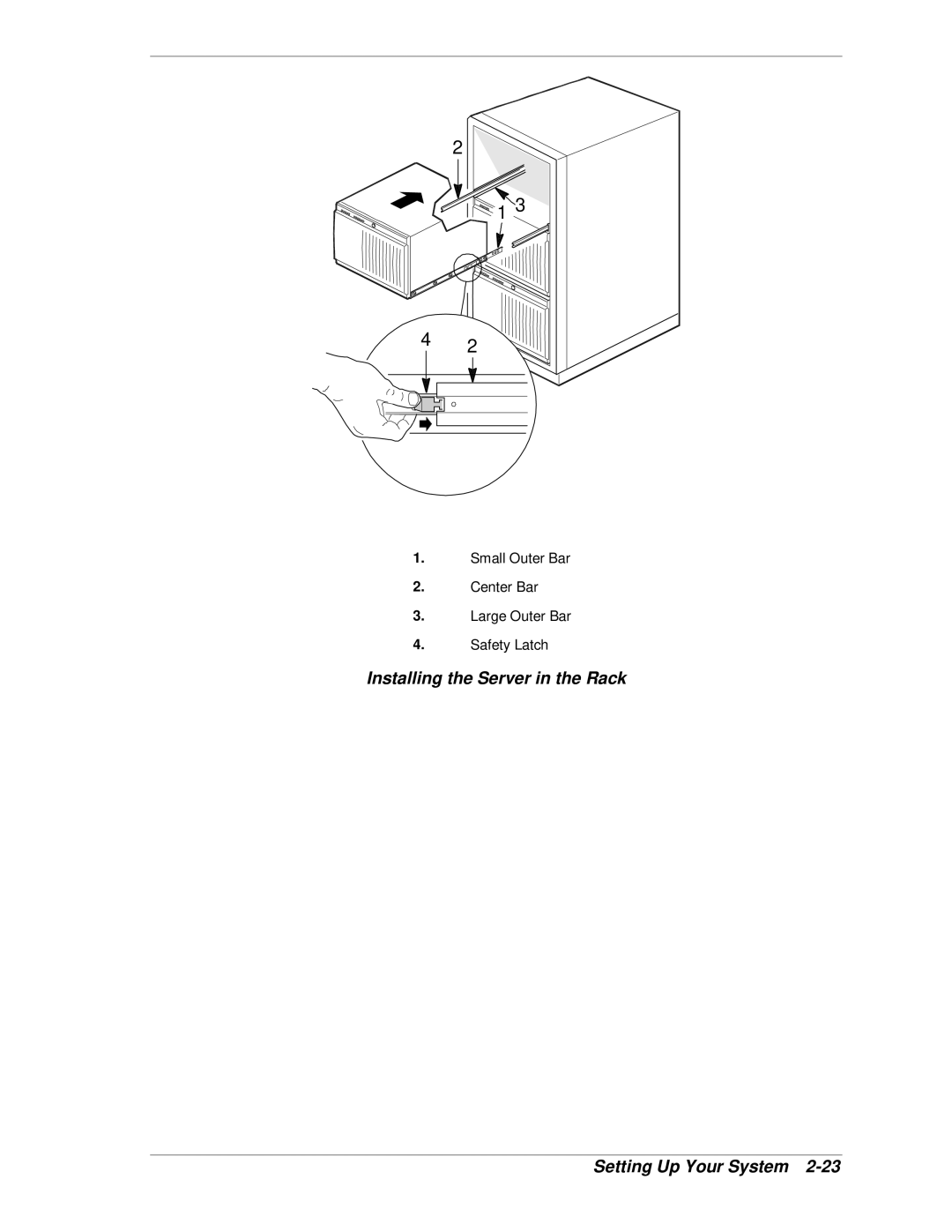
1.
Small Outer Bar
2.
Center Bar
3.
Large Outer Bar
4.
Safety Latch
Installing the Server in the Rack
Setting Up Your System
2-23
Page 42
Page 44
Page 43
Image 43
Page 42
Page 44
Contents
Server MH4500
Page
Server MH4500
Proprietary Notice and Liability Disclaimer
Contents
Iv Contents
Configuring Your System
System Cabling
Emergency Management Port
Vi Contents
System Overview
Page
System Chassis Features
System Chassis
Power Supplies
Removable Media Device Bays Memory Module Connector
System Cooling
Peripheral Bays
System Board Features
D E CC BB
System Board System Overview
System Memory
Pentium II Xeon Processor
Expansion Slots
IDE Controller
Real-Time Clock/Calendar
Scsi Controllers
Parallel Port
Video Controller
Peripheral Controller
Serial Ports
Mechanical Locks and Monitoring
System Security Features
External Device Connectors
System Board Management Controller BMC
System Overview
Setting Up Your System
Selecting a Site
Setting Up Your System
Unpacking the System
Front View
Getting Familiar with the System
Front Features and Controls Setting Up Your System
Rear View
Rear Features and Controls Setting Up Your System
Connecting Peripherals
Installing the System
Connecting the Power Cords
Powering On the System
Setting Up Your System
Converting to a Rack Mount Server Unit
Equipment Rack Warnings and Cautions
Converting the System Pedestal Unit
Removing the Cover Screws Setting Up Your System
Removing the System Unit Covers
Replacing the Bezel Frame
Replacing the Bezel Frame Setting Up Your System
Install the two chassis handles on the chassis as follows
Installing the Chassis Handles
Attaching the Chassis Handles
Attaching the Outer Slide Bars to the Chassis
Releasing the Small Outer Bar Setting Up Your System
Page
Preparing the Rack
Installing the Rack Extension Brackets
Typical Equipment Rack
Installing the Extension Brackets
Installing the Slider Assemblies
Installing the Slider Assembly
Installing the Rack Unit in the Rack
Setting Up Your System
Installing the Server in the Rack Setting Up Your System
Page
Configuring Your System
Configuring Your System
Menu Bar Selections
Using the Bios Setup Utility
Setup Menu Keys
Key Function in Setup Menu
44 MB
Disabled
Main Menu
Main Menu
Primary IDE Master and Slave Submenu
Primary IDE Master and Slave Submenu
Advanced Menu
Advanced Menu
Keyboard Submenu
Keyboard Submenu
PCI Device, Embedded Scsi Submenu
PCI Configuration Submenus
0080h
Scsi a & B On
Device Configuration Submenu
Device Configuration Submenu
PCI Devices Submenu
378
Advanced Chipset Control Submenu
3F8
2F8
Security Menu
Feature Choice Description Your Setting
Security Menu
Advanced Chipset Control Submenu
Normal
System Board Jumpers
AT&FS0=1S14=0
Server Menu
Server Menu
+++
System Management Submenu
System Management Submenu
Console Redirection Submenu
Boot Menu
Boot Device Priority Submenu
Boot Menu
Hard Drive Submenu
Boot Device Priority Submenu
Boot Priority Device Description Your Setting
Hard Drive Submenu
Exit Menu
Using the Symbios Scsi Utility
Running the Symbios Scsi Utility
Exit Menu
Key Action
Changing the Adapter and Device Configurations
Symbios Scsi Utility Main Menu
Active Keys
Adapter Setup Screen
Scsi Removable Media Devices
Scsi Hard Disk Drives
Factory Installed Controller
Using the Optional RAID Controller
Add-on Controller
Factory RAID Configurations with Scsi Hard Drives
Daccf Configuration Utility
Number RAID Level Hard Drives Configured Array Description
System Board Jumpers Configuring Your System
Configuring System Board Jumpers
10, Normal
Function Pins default in bold What it Does at System Reset
Moving System Board Jumpers
System Board Jumper J6J1 Summary
Clearing and Changing Passwords
Resetting the Cmos Nvram
Nvram cleared by jumper Press F2 to enter Setup
Configuring Your System
Page
Upgrading Your System
Upgrading Your System
Observing Static Precautions
Preparing the Equipment Log
Preparing Your System for Upgrade
Removing the Access Cover
Removing/Installing the Access Cover
Installing the Access Cover
Opening the Subchassis and Electronics Bay
Opening the Subchassis and Electronics Bay
Closing the Subchassis and Electronics Bay
Upgrading the System Board
Replacing the Real-time Clock Battery
Replacing the Real-Time Clock Battery
Installing a Processor Cartridge
Installing/Removing the Processor Cartridge
Installing a Processor S.E.C. Cartridge
Upgrading Your System
Opening the Latch
Removing a Processor Cartridge
Removing the Processor
Installing Dimm Modules
Memory Module
Removing the Memory Module
Removing the Memory Module
Installing DIMMs
Installing the Dimm
Removing DIMMs
Installing the Memory Module
Installing Option Boards
Locating the PCI and ISA Slots
Installation Considerations
Memory Option Board
Controller/Adapter Hardware Configurations
Installing an Option Board
Option Board Hardware Configurations
Removing an Option Board
Installing an Option Board
Upgrading Your System
2-Inch Scsi Hard Drive Bay Location
Installing Hard Disk Drives
Installing the Hard Drive Carrier
Installing an Optional Scsi Hard Disk Drive
Hot-Swapping a Scsi Hard Disk Drive
Installing an Optional Scsi Hard Drive
Unlocking the Carrier
Installing Removable Media Devices
Installing a 5 1/4-Inch Media Device
Removing the EMI Shield
Installing the Device Rails
Removing a 5 1/4-Inch Media Device
Page
Solving Problems
Troubleshooting Checklists
Static Precautions
Solving Problems
Initial System Startup
After System Has Been Running Correctly
Running New Application Software
Preparing the System for Diagnostic Testing
Additional Troubleshooting Procedures
Monitoring Post
Post Keys and Errors
Action/Message Description
Verifying Proper Operation of Key System Indicators
Specific Problems and Corrective Actions
Confirming Loading of the Operating System
No Beep Code
Power LED Does Not Light
No Characters Appear on Screen
System Cooling Fans Does Not Rotate
Characters are Distorted or Incorrect
Hard Disk Drive Activity LED Does Not Light
Diskette Drive Activity LED Does Not Light
Press F2 Key to Enter Setup Prompt Does Not Display
Problems with Application Software
CD ROM Drive Activity Light Does Not Light
Enable F2 Prompt by Changing a Jumper and Using SSU
Enable F2 Prompt by Using SSU
Bootable CD-ROM Is Not Detected
Problems with the Network
PCI Installation Tips
Message Description
Bios User’s Information
Error and Status Messages
Bios Messages
Setup
Post Tests
Messages and Beep Codes
Code Beeps Post Routine Description
Reset Programmable Interrupt Controller
Set key click if enabled
Clear hugh ES segment register
Post Error Codes and Messages
Post Error Codes and Messages
Code Error message Pause on Error
Post Error Codes and Messages
Post Error Codes and Messages
Page
System Cabling
Before You Begin
Standard Configuration
System Cabling
System Cabling A-3
Power Cabling
Diskette Drive Data Cabling
Scsi Cabling
Scsi Distribution Backplane
Standard Cabling Configuration System Cabling
System Cabling A-5
RAID Configuration
Page
System Setup Utility
System Setup Utility
Creating SSU Diskettes
System Setup Utility B-3
Running the SSU
Customizing the SSU
System Setup Utility Main Menu Window
Launching a Task
System Setup Utility B-5
Resource Configuration Add-in RCA Window
Defining an ISA Board
System Setup Utility B-7
RCA Window
Modifying Resources
Adding and Removing ISA Boards
Adding and Removing ISA Boards Window
Configuration Window
Recommended Resource Settings
System Setup Utility B-9
System Group Normal Setting Your Configuration
Recommended Resource Settings
System Resource Usage Window
Multiboot Add-in MBA Window
System Setup Utility B-11
System Resource Usage
System Event Log SEL Window
Password Administration PWA Window
SDR Manager Menus
System Setup Utility B-13
Sensor Data Record SDR Manager Add-In Window
SEL Viewer Menus
Field Replaceable Unit FRU Manager Add-In Window
Exiting the SSU
FRU Manager Menus
Emergency Management Port
Management Console
Emergency Management Port Configuration
How the EMP Works
Emergency Management Port
EMP in Command State Emergency Management Port C-3
Mode Server Powered Off During Post After OS boots
EMP Access Modes Server Configured for Console Redirect
Console in Redirect State
EMP Access Modes Server Not Configured for Console Redirect
EMP Requirements and Configurations
Emergency Management Port C-5
System Management Submenu
Setting Up the Server for the EMP
Console Redirection Submenu
Emergency Management Port C-7
Main EMP Window
Toolbar
Status Bar
Server Control Operations
EMP Console Main Menu
Connect to Remote Server
Emergency Management Port C-9
Connect Dialog
Power On/Off Dialog
Power On/Off
Reset Dialog
Reset
Emergency Management Port C-11
Phonebook Dialog
Phonebook
Emergency Management Port C-13
Management Plug-ins
SEL Viewer
SEL Viewer Menu Options
Connect View
SDR Viewer
Emergency Management Port C-15
FRU Viewer
SDR Viewer Menu Options
FRU Viewer Menu Options
FRU and SDR Load Utility
When to Run the Frusdr Load Utility
How You Use the Frusdr Load Utility
Command Line Format
Command Line Format
What You Need to Do
Displaying Usage Information
Parsing the Command Line
Usage Frusdr
Displaying a Given Area
Using Specified CFG File
Emergency Management Port C-19
Configuration File
Emergency Management Port C-21
Cleaning Up and Exiting
Page
Glossary
Glossary
Process of loading the operating system into memory
See math coprocessor
See EMS
073,741,824 bytes. See also byte
Bytes. See also byte
Nvram
Power-On-Self-Test
Information sent sequentially, one bit at a time
To record or store information to a storage device
Equipment Log
Equipment Log
Equipment Log
Index-1
Index
Index-2
SCU
Index-3
Page
Page
456-00008-003
Top
Page
Image
Contents