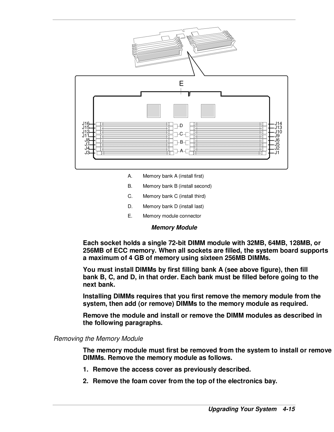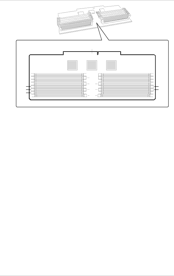
E
J16![]()
![]()
J15![]()
![]()
J12![]()
![]()
J11![]()
![]()
J8
J7
J4
J3![]()
![]()
![]()
![]() D
D
![]()
![]() C
C ![]()
![]()
![]()
![]() B
B![]()
![]()
![]()
![]() A
A![]()
![]()
A.Memory bank A (install first)
B.Memory bank B (install second)
C.Memory bank C (install third)
D.Memory bank D (install last)
E.Memory module connector
![]()
![]() J14
J14
![]()
![]() J13
J13
![]()
![]() J10
J10
![]()
![]() J9 J6 J5
J9 J6 J5 ![]()
![]() J2
J2 ![]()
![]() J1
J1
Memory Module
Each socket holds a single
You must install DIMMs by first filling bank A (see above figure), then fill bank B, C, and D, in that order. Each bank must be filled before going to the next bank.
Installing DIMMs requires that you first remove the memory module from the system, then add (or remove) DIMMs to the memory module as required.
Remove the module and install or remove the DIMM modules as described in the following paragraphs.
Removing the Memory Module
The memory module must first be removed from the system to install or remove DIMMs. Remove the memory module as follows.
1.Remove the access cover as previously described.
2.Remove the foam cover from the top of the electronics bay.