NEC MH4500 manual Installation Considerations, A B C

Models: MH4500

1 186
Download 186 pages 30.11 Kb
Page 90
Image 90
A

A

B

C

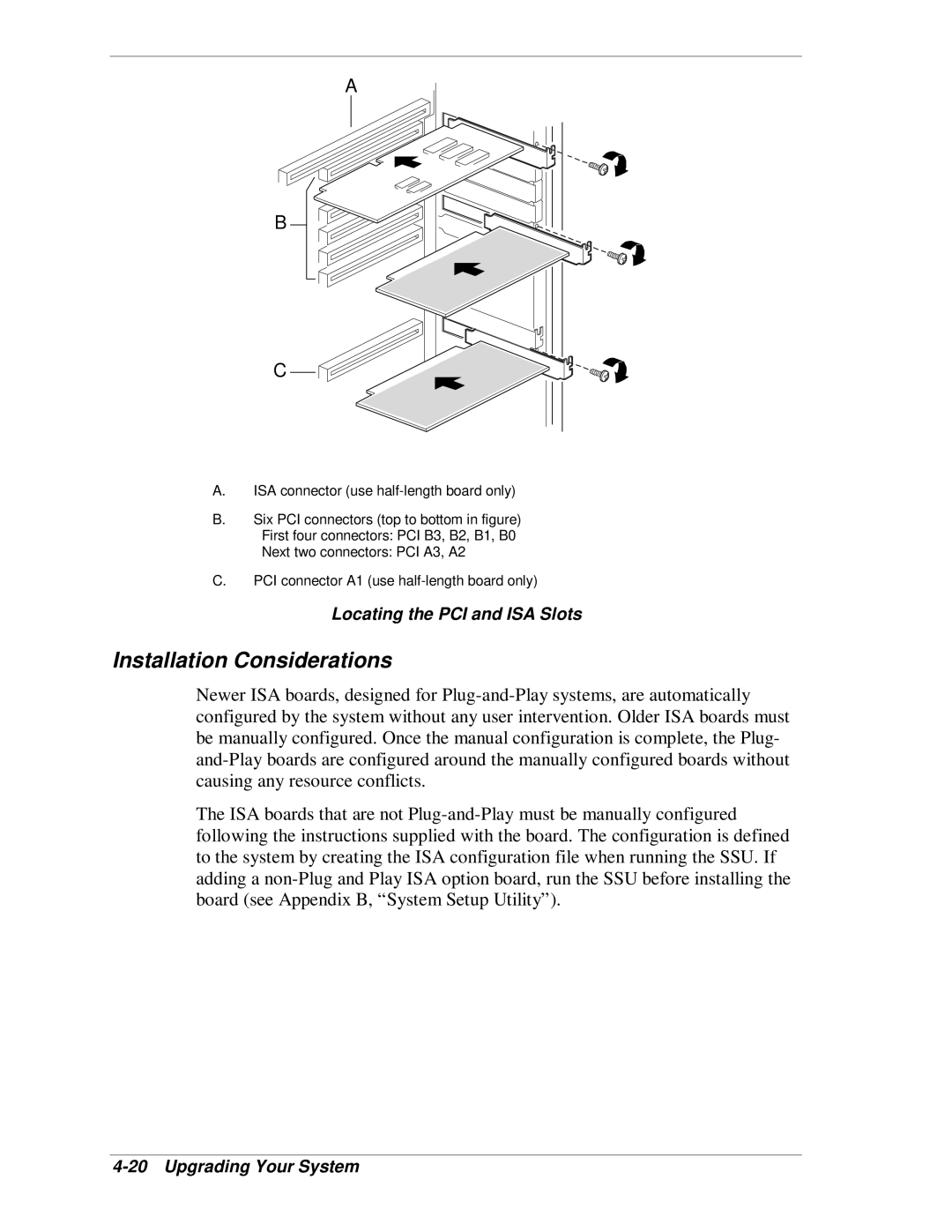
A.ISA connector (use half-length board only)

B.Six PCI connectors (top to bottom in figure) First four connectors: PCI B3, B2, B1, B0 Next two connectors: PCI A3, A2

C.PCI connector A1 (use half-length board only)

Locating the PCI and ISA Slots

Installation Considerations

Newer ISA boards, designed for Plug-and-Play systems, are automatically configured by the system without any user intervention. Older ISA boards must be manually configured. Once the manual configuration is complete, the Plug- and-Play boards are configured around the manually configured boards without causing any resource conflicts.

The ISA boards that are not Plug-and-Play must be manually configured following the instructions supplied with the board. The configuration is defined to the system by creating the ISA configuration file when running the SSU. If adding a non-Plug and Play ISA option board, run the SSU before installing the board (see Appendix B, “System Setup Utility”).

4-20 Upgrading Your System

Page 90
Image 90
NEC MH4500 manual Installation Considerations, A B C