Nortel Networks 10BASE-T manual Verifying the Installation Using the LEDs, Power-Up Sequence

Models: 10BASE-T

1 330
Download 330 pages 13.91 Kb
Page 132
Image 132

Using the BayStack 410-24T 10BASE-T Switch

Verifying the Installation

When power is applied to the switch, power-on self-tests are run. You can verify proper operation of the BayStack 410-24T switch by observing the front-panel LEDs or by viewing the self-test results as displayed in the BayStack 410-24T switch Self-Test screen.

Verifying the Installation Using the LEDs

To verify the installation using the LEDs, check that the switch power-up sequence is as described in Table 2-1:

Table 2-1. Power-Up Sequence

Stage Description

LED indication

1Immediately after AC power is applied to the switch, DC power is available to the switch’s internal circuitry.

The Power LED turns on within 5 seconds (Figure 2-10). If the Power LED does not turn on, verify that power is available at the AC power outlet and that the power cable is fastened securely at both ends. If the Power LED remains off, contact the sales agent or the customer service representative from whom you purchased the switch.

2 The switch initiates a self-test. As subroutines are initiated by the self-test, the port status LEDs flash various patterns. When the switch passes the self-test (within 10 seconds), the Status LED turns on (Figure 2-10).

If a nonfatal error occurs during self-test, the Status LED blinks.

If the switch fails the
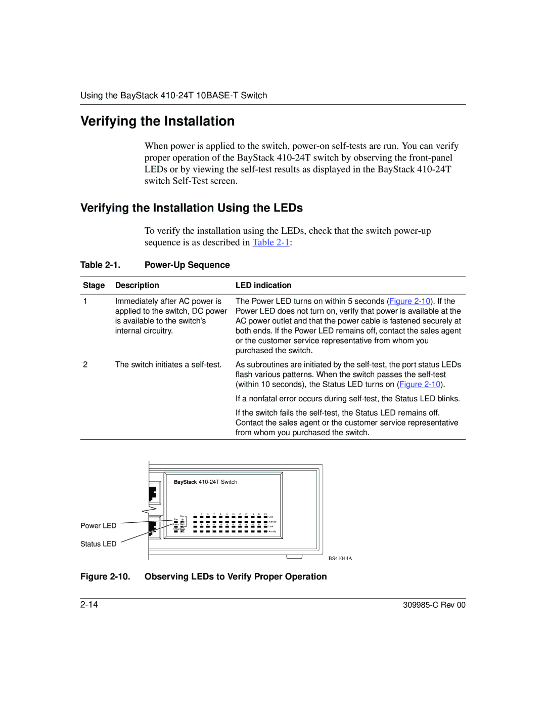
 self-test, the Status LED remains off. Contact the sales agent or the customer service representative from whom you purchased the switch.

Power LED

Status LED

BayStack 410-24T Switch


Cas

1


3


5


7


9


11

13


15


17


19


21


23


Link

Pwr Up


Activity


Status Dwn

2


4


6


8


10


12

14


16


18


20


22


24

Link


RPSU Base

Activity

BS41044A

Figure 2-10. Observing LEDs to Verify Proper Operation

2-14

309985-C Rev 00

Page 132
Image 132
Nortel Networks 10BASE-T manual Verifying the Installation Using the LEDs, Power-Up Sequence