Introduction to the BayStack 410-24T Switch
BayStack 400-ST1 Cascade Module
The
1
| Unit Select |
|
Cascade A Out | Base | Cascade A In |
|
| 4 |
2 | 3 |
|
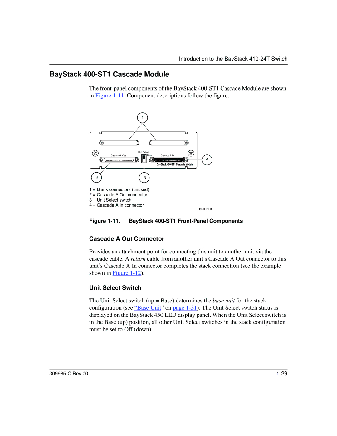
1 = Blank connectors (unused)
2 = Cascade A Out connector
3 = Unit Select switch
4 = Cascade A In connector
BS0031B
Figure 1-11. BayStack 400-ST1 Front-Panel Components
Cascade A Out Connector
Provides an attachment point for connecting this unit to another unit via the cascade cable. A return cable from another unit’s Cascade A Out connector to this unit’s Cascade A In connector completes the stack connection (see the example shown in Figure
Unit Select Switch
The Unit Select switch (up = Base) determines the base unit for the stack configuration (see “Base Unit” on page
|