Using the BayStack 410-24T 10BASE-T Switch

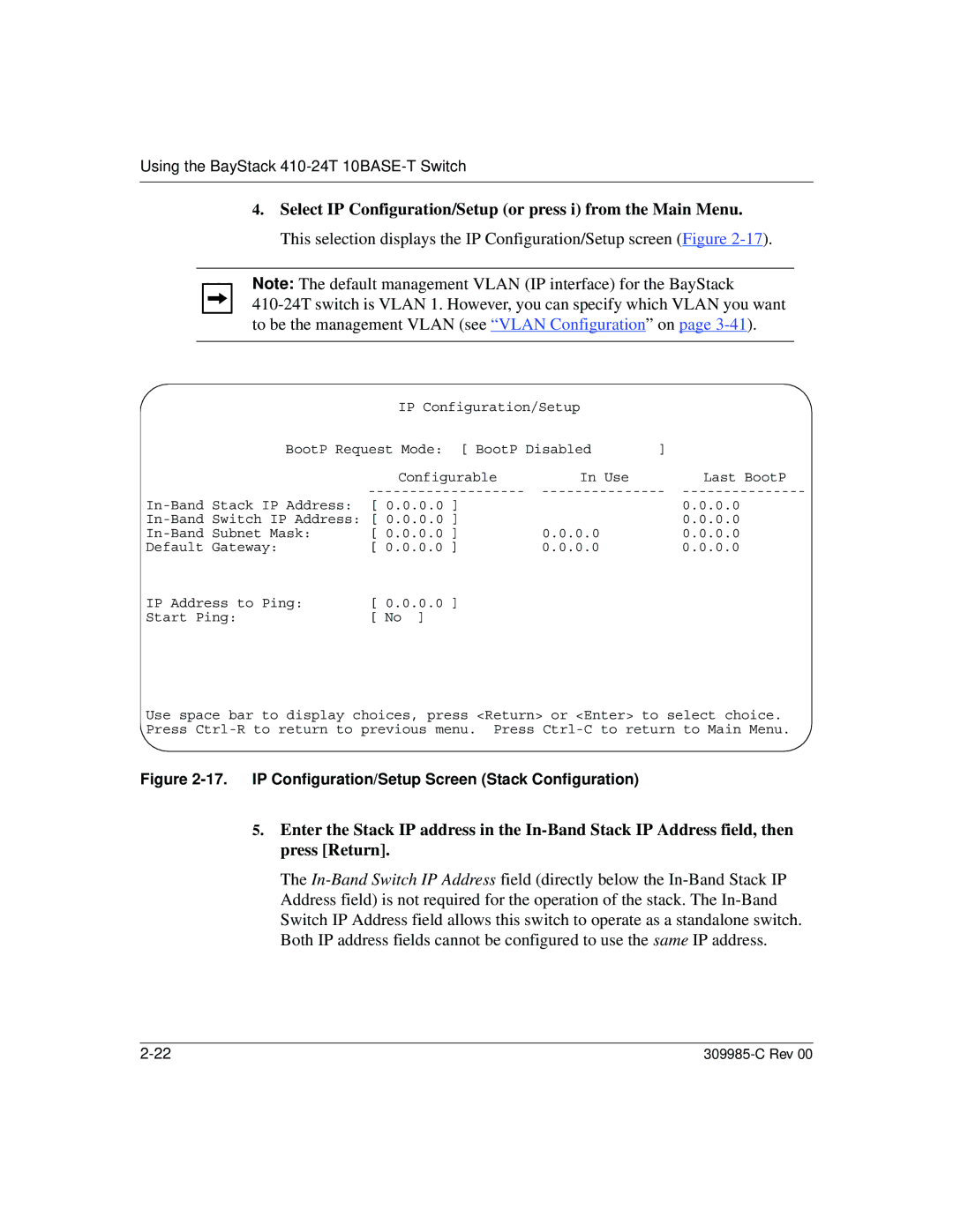
4.Select IP Configuration/Setup (or press i) from the Main Menu. This selection displays the IP Configuration/Setup screen (Figure 2-17).

Note: The default management VLAN (IP interface) for the BayStack

410-24T switch is VLAN 1. However, you can specify which VLAN you want to be the management VLAN (see “VLAN Configuration” on page 3-41).


IP Configuration/Setup


BootP Request Mode: [ BootP Disabled

]


Configurable

In Use


Last BootP


-------------------

---------------

---------------

In-Band Stack IP Address:

[ 0.0.0.0 ]


0.0.0.0

In-Band Switch IP Address: [ 0.0.0.0 ]


0.0.0.0

In-Band Subnet Mask:

[ 0.0.0.0 ]

0.0.0.0


0.0.0.0

Default Gateway:

[ 0.0.0.0 ]

0.0.0.0


0.0.0.0

IP Address to Ping:

[ 0.0.0.0 ]


Start Ping:

[ No ]


Use space bar to display choices, press <Return> or <Enter> to select choice. Press Ctrl-R to return to previous menu. Press Ctrl-C to return to Main Menu.

Figure 2-17. IP Configuration/Setup Screen (Stack Configuration)

5.Enter the Stack IP address in the In-Band Stack IP Address field, then press [Return].

The In-Band Switch IP Address field (directly below the In-Band Stack IP Address field) is not required for the operation of the stack. The In-Band Switch IP Address field allows this switch to operate as a standalone switch. Both IP address fields cannot be configured to use the same IP address.

2-22

309985-C Rev 00

Page 140
Image 140
Nortel Networks 10BASE-T manual IP Configuration/Setup Screen Stack Configuration