Using the BayStack 410-24T 10BASE-T Switch
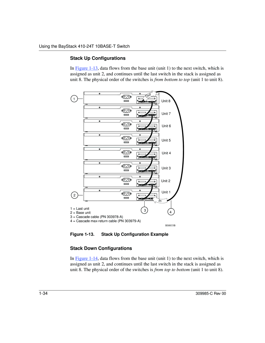
Stack Up Configurations
In Figure
1
t u O
Unit 8
Unit 7
Unit 6
Unit 5
Unit 4
Unit 3
Unit 2
2
![]() In
In
Unit 1
1 | = Last unit | 3 | |
2 | = Base unit | ||
| |||
3 | = Cascade cable (PN |
| |
4 | = Cascade |
|
4
BS0033B
Figure 1-13. Stack Up Configuration Example
Stack Down Configurations
In Figure