Using the BayStack
Front Panel
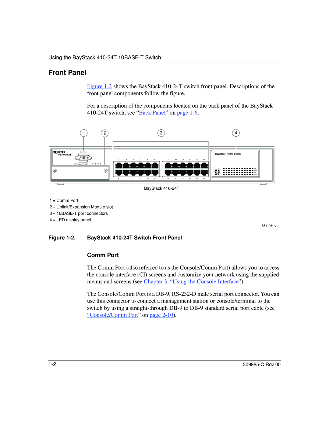
Figure 1-2 shows the BayStack 410-24T switch front panel. Descriptions of the front panel components follow the figure.
For a description of the components located on the back panel of the BayStack 410-24T switch, see “Back Panel” on page 1-6.
1 | 2 | 3 | 4 |
Comm Port |
|
|
|
|
|
|
|
|
|
|
|
|
|
| 1 | 3 |
| 5 | 7 | 9 | 11 | 13 | 15 | 17 | 19 | 21 | 23 |
Uplink/Expansion Module | 25 26 27 28 |
|
|
|
|
|
|
|
|
|
|
|
|
| 2 | 4 | 6 |
| 8 | 10 | 12 | 14 | 16 | 18 | 20 | 22 | 24 |
BayStack
1 = Comm Port
2 = Uplink/Expansion Module slot
3 =
4 = LED display panel
| 1 |
Cas | Link |
Pwr Up
Activity
Status Dwn
Link
RPSU Base
Activity
BS41064A
Figure 1-2. BayStack 410-24T Switch Front Panel
Comm Port
The Comm Port (also referred to as the Console/Comm Port) allows you to access the console interface (CI) screens and customize your network using the supplied menus and screens (see Chapter 3, “Using the Console Interface”).
The Console/Comm Port is a