Using the BayStack
Fail-Safe Stack Application
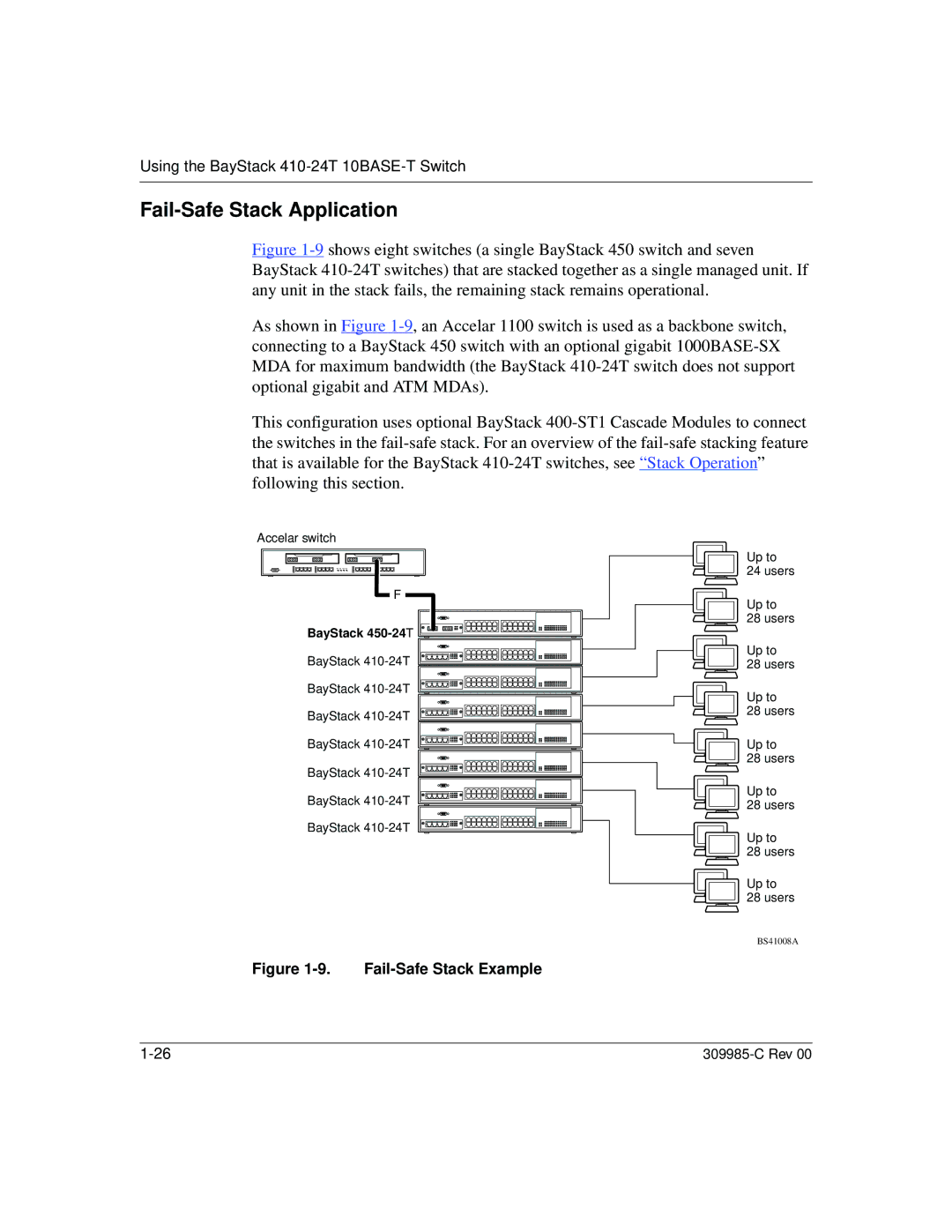
Figure 1-9 shows eight switches (a single BayStack 450 switch and seven BayStack 410-24T switches) that are stacked together as a single managed unit. If any unit in the stack fails, the remaining stack remains operational.
As shown in Figure 1-9, an Accelar 1100 switch is used as a backbone switch, connecting to a BayStack 450 switch with an optional gigabit 1000BASE-SX MDA for maximum bandwidth (the BayStack 410-24T switch does not support optional gigabit and ATM MDAs).
This configuration uses optional BayStack 400-ST1 Cascade Modules to connect the switches in the fail-safe stack. For an overview of the fail-safe stacking feature that is available for the BayStack 410-24T switches, see “Stack Operation” following this section.
Accelar switch
F
BayStack |
BayStack
BayStack
BayStack
BayStack
BayStack
BayStack
BayStack
Figure 1-9. Fail-Safe Stack Example
Up to
24 users
Up to
28 users
Up to
28 users
Up to
28 users
Up to
28 users
Up to
28 users
Up to
28 users
Up to
28 users
BS41008A
