Introduction to the BayStack 410-24T Switch
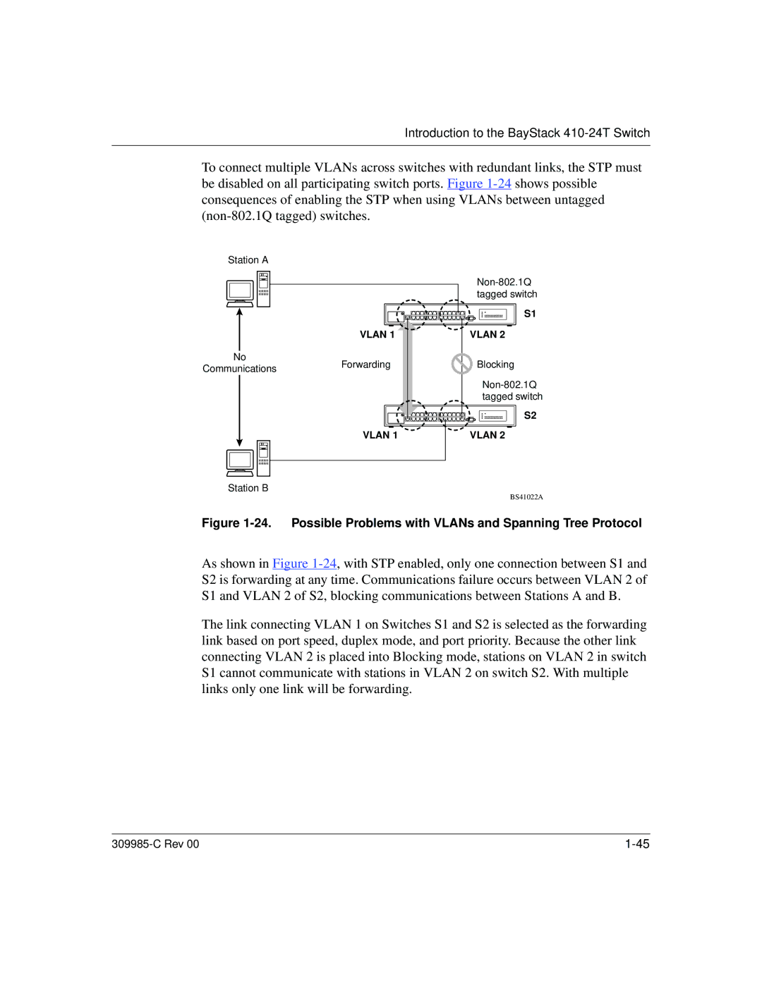
To connect multiple VLANs across switches with redundant links, the STP must be disabled on all participating switch ports. Figure
Station A
VLAN 1
No
CommunicationsForwarding
VLAN 1
Station B
S1
VLAN 2
Blocking
S2
VLAN 2
BS41022A
Figure 1-24. Possible Problems with VLANs and Spanning Tree Protocol
As shown in Figure
The link connecting VLAN 1 on Switches S1 and S2 is selected as the forwarding link based on port speed, duplex mode, and port priority. Because the other link connecting VLAN 2 is placed into Blocking mode, stations on VLAN 2 in switch S1 cannot communicate with stations in VLAN 2 on switch S2. With multiple links only one link will be forwarding.
|