Using the BayStack
Table 1-1. BayStack 410-24T Switch LED Descriptions (continued)
Label | Type | Color | State | Meaning |
|
|
|
|
|
|
|
|
| This automatic process is a temporary safeguard only. If |
|
|
|
| the stack configuration loses power, the temporary base |
|
|
|
| unit will not power up as the base unit when power is |
|
|
|
| restored. For this reason, you should always assign the |
|
|
|
| temporary base unit as the base unit (set the Unit Select |
|
|
|
| switch to Base) until the failed unit is repaired or replaced. |
Link | 10 Mb/s port | Green | On | The corresponding port is set to operate at 10 Mb/s and |
| speed indicator |
|
| the link is good. |
|
| Green | Blinking | The corresponding port has been disabled by software. |
|
|
| Off | The link connection is bad or there is no connection to |
|
|
|
| this port. |
Activity | Port activity | Green | Blinking | Indicates network activity for the corresponding port. A |
|
|
|
| high level of network activity can cause the LEDs to |
|
|
|
| appear to be on continuously. |
|
|
|
|
|
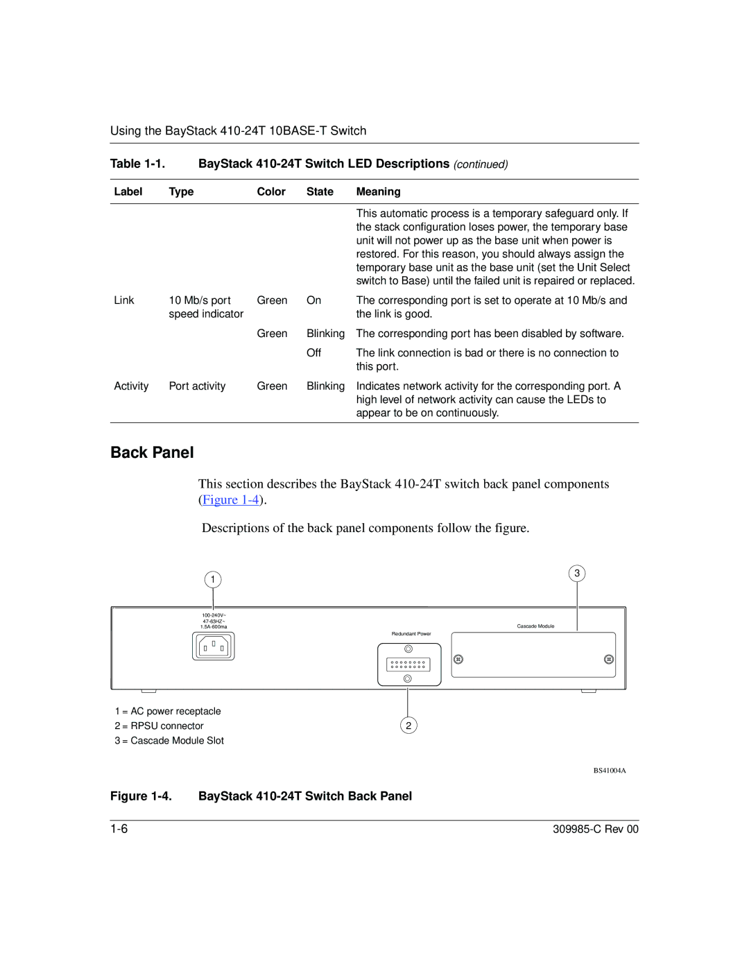
Back Panel
This section describes the BayStack
Descriptions of the back panel components follow the figure.
1 | 3 |
| |
| |
Cascade Module | |
Redundant Power
1 = AC power receptacle
2 = RPSU connector | 2 |
3 = Cascade Module Slot
BS41004A