Using the BayStack 410-24T 10BASE-T Switch
BayStack
IP Configuration/Setup...
SNMP Configuration...
System Characteristics...
Switch Configuration...
Console/Comm Port Configuration...
Display Hardware Units...
Spanning Tree Configuration...
TELNET/SNMP Mgr List Configuration...
Software Download...
Configuration File...
Display Event Log
Save Current Settings
Reset
Reset to Default Settings
Logout
Use arrow keys to highlight option, press <Return> or <Enter> to select option.
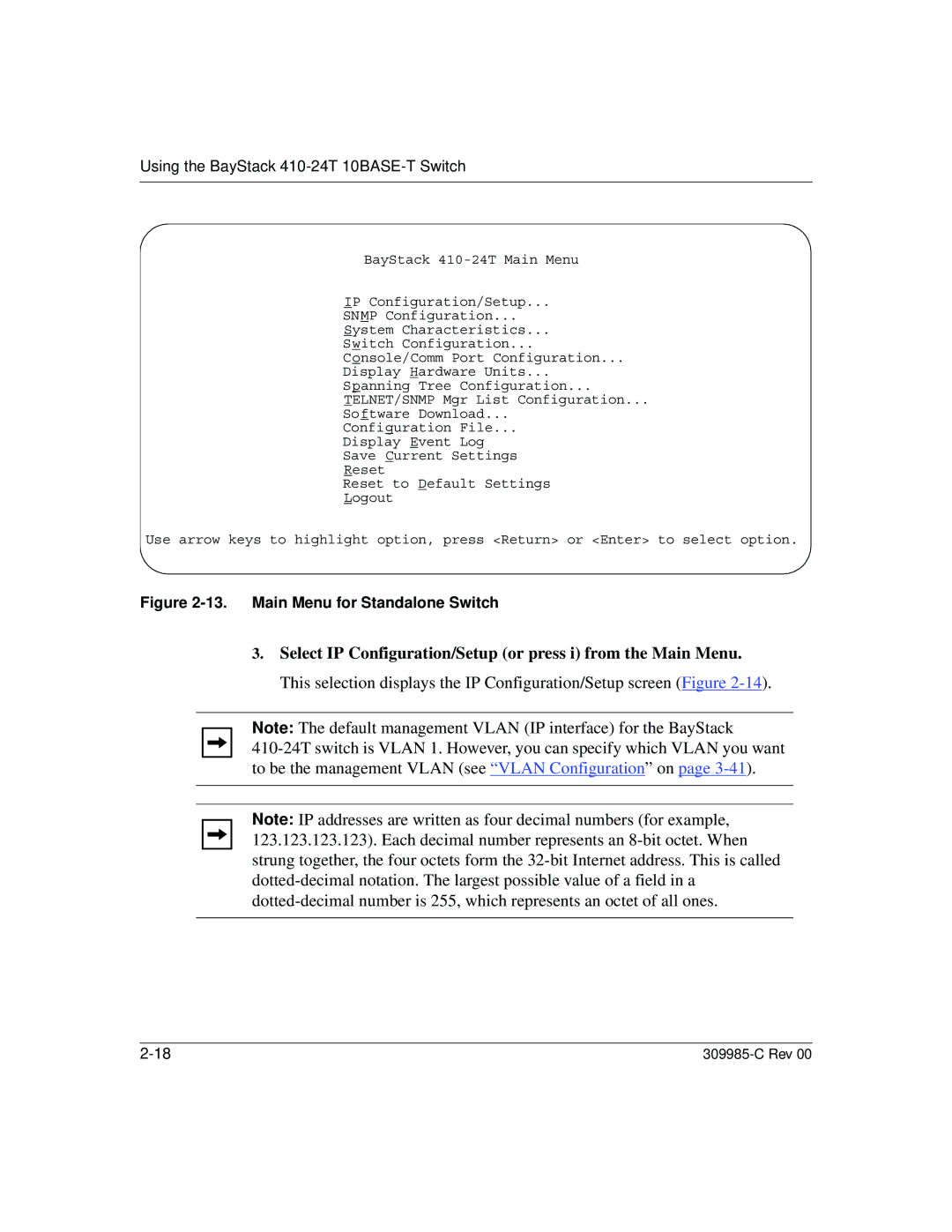
Figure 2-13. Main Menu for Standalone Switch
3.Select IP Configuration/Setup (or press i) from the Main Menu. This selection displays the IP Configuration/Setup screen (Figure
Note: The default management VLAN (IP interface) for the BayStack
Note: IP addresses are written as four decimal numbers (for example, 123.123.123.123). Each decimal number represents an
