Using the BayStack
LED Display Panel
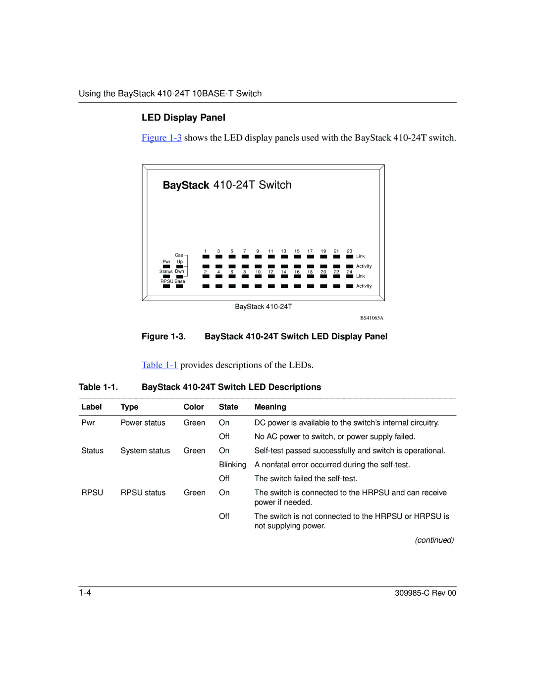
Figure 1-3 shows the LED display panels used with the BayStack 410-24T switch.
BayStack 410-24T Switch
Cas Pwr Up
Status Dwn
RPSU Base
1 |
| 3 |
| 5 |
| 7 |
| 9 |
| 11 | 13 |
| 15 |
| 17 |
| 19 |
| 21 |
| 23 | Link | |
|
|
|
|
|
|
|
|
|
|
|
|
|
|
|
|
|
|
|
|
|
|
| |
|
|
|
|
|
|
|
|
|
|
|
|
|
|
|
|
|
|
|
|
|
|
| Activity |
|
|
|
|
|
|
|
|
|
|
|
|
|
|
|
|
|
|
|
|
|
|
| |
2 |
| 4 |
| 6 |
| 8 |
| 10 |
| 12 | 14 |
| 16 |
| 18 |
| 20 |
| 22 |
| 24 | Link | |
|
|
|
|
|
|
|
|
|
|
|
|
|
|
|
|
|
|
|
|
|
|
| |
Activity
BayStack
BS41065A
Figure 1-3. BayStack 410-24T Switch LED Display Panel
Table 1-1 provides descriptions of the LEDs.
Table | BayStack | |||
|
|
|
|
|
Label | Type | Color | State | Meaning |
|
|
|
|
|
Pwr | Power status | Green | On | DC power is available to the switch’s internal circuitry. |
|
|
| Off | No AC power to switch, or power supply failed. |
Status | System status | Green | On | |
|
|
| Blinking | A nonfatal error occurred during the |
|
|
| Off | The switch failed the |
RPSU | RPSU status | Green | On | The switch is connected to the HRPSU and can receive |
|
|
|
| power if needed. |
|
|
| Off | The switch is not connected to the HRPSU or HRPSU is |
|
|
|
| not supplying power. |
(continued)