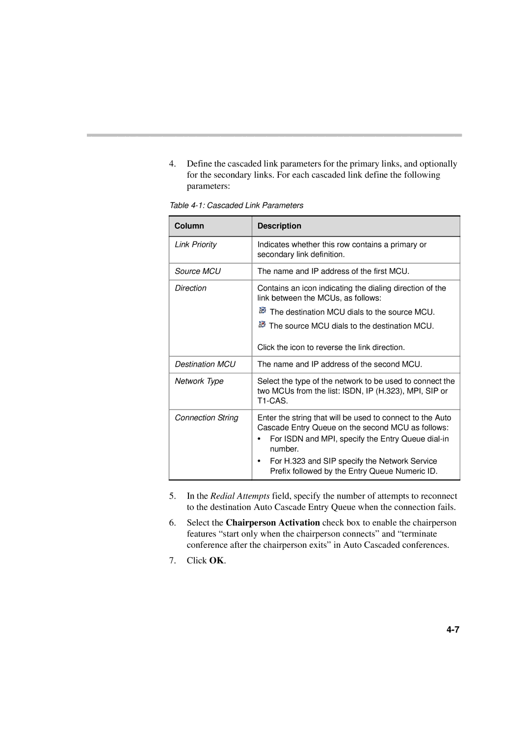
4.Define the cascaded link parameters for the primary links, and optionally for the secondary links. For each cascaded link define the following parameters:
Table
Column | Description |
|
|
Link Priority | Indicates whether this row contains a primary or |
| secondary link definition. |
|
|
Source MCU | The name and IP address of the first MCU. |
|
|
Direction | Contains an icon indicating the dialing direction of the |
| link between the MCUs, as follows: |
| The destination MCU dials to the source MCU. |
| The source MCU dials to the destination MCU. |
| Click the icon to reverse the link direction. |
|
|
Destination MCU | The name and IP address of the second MCU. |
|
|
Network Type | Select the type of the network to be used to connect the |
| two MCUs from the list: ISDN, IP (H.323), MPI, SIP or |
|
|
|
|
Connection String | Enter the string that will be used to connect to the Auto |
| Cascade Entry Queue on the second MCU as follows: |
•For ISDN and MPI, specify the Entry Queue
•For H.323 and SIP specify the Network Service Prefix followed by the Entry Queue Numeric ID.
5.In the Redial Attempts field, specify the number of attempts to reconnect to the destination Auto Cascade Entry Queue when the connection fails.
6.Select the Chairperson Activation check box to enable the chairperson features “start only when the chairperson connects” and “terminate conference after the chairperson exits” in Auto Cascaded conferences.
7.Click OK.
