INSTALLATION REFERENCE
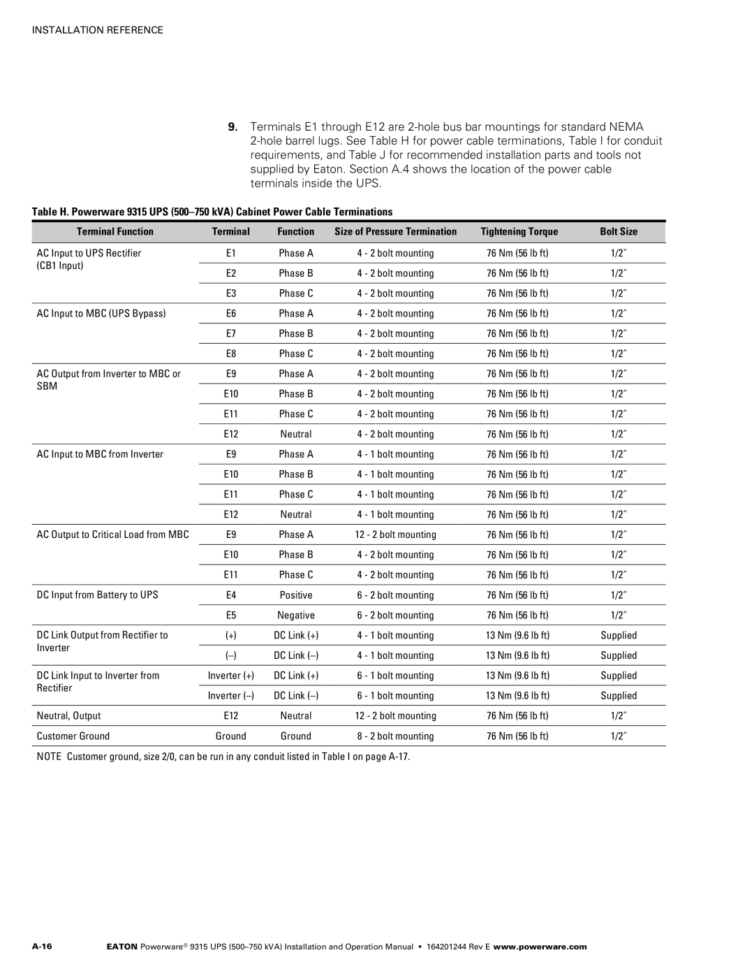
9.Terminals E1 through E12 are 2‐hole bus bar mountings for standard NEMA 2‐hole barrel lugs. See Table H for power cable terminations, Table I for conduit requirements, and Table J for recommended installation parts and tools not supplied by Eaton. Section A.4 shows the location of the power cable terminals inside the UPS.
Table H. Powerware 9315 UPS
Terminal Function | Terminal | Function | Size of Pressure Termination | Tightening Torque | Bolt Size | |
|
|
|
|
|
| |
AC Input to UPS Rectifier | E1 | Phase A | 4 - 2 bolt mounting | 76 Nm (56 lb ft) | 1/2” | |
(CB1 Input) |
|
|
|
|
| |
E2 | Phase B | 4 - 2 bolt mounting | 76 Nm (56 lb ft) | 1/2” | ||
| ||||||
|
|
|
|
|
| |
| E3 | Phase C | 4 - 2 bolt mounting | 76 Nm (56 lb ft) | 1/2” | |
|
|
|
|
|
| |
AC Input to MBC (UPS Bypass) | E6 | Phase A | 4 - 2 bolt mounting | 76 Nm (56 lb ft) | 1/2” | |
|
|
|
|
|
| |
| E7 | Phase B | 4 - 2 bolt mounting | 76 Nm (56 lb ft) | 1/2” | |
|
|
|
|
|
| |
| E8 | Phase C | 4 - 2 bolt mounting | 76 Nm (56 lb ft) | 1/2” | |
|
|
|
|
|
| |
AC Output from Inverter to MBC or | E9 | Phase A | 4 - 2 bolt mounting | 76 Nm (56 lb ft) | 1/2” | |
SBM |
|
|
|
|
| |
E10 | Phase B | 4 - 2 bolt mounting | 76 Nm (56 lb ft) | 1/2” | ||
| ||||||
|
|
|
|
|
| |
| E11 | Phase C | 4 - 2 bolt mounting | 76 Nm (56 lb ft) | 1/2” | |
|
|
|
|
|
| |
| E12 | Neutral | 4 - 2 bolt mounting | 76 Nm (56 lb ft) | 1/2” | |
|
|
|
|
|
| |
AC Input to MBC from Inverter | E9 | Phase A | 4 - 1 bolt mounting | 76 Nm (56 lb ft) | 1/2” | |
|
|
|
|
|
| |
| E10 | Phase B | 4 - 1 bolt mounting | 76 Nm (56 lb ft) | 1/2” | |
|
|
|
|
|
| |
| E11 | Phase C | 4 - 1 bolt mounting | 76 Nm (56 lb ft) | 1/2” | |
|
|
|
|
|
| |
| E12 | Neutral | 4 - 1 bolt mounting | 76 Nm (56 lb ft) | 1/2” | |
|
|
|
|
|
| |
AC Output to Critical Load from MBC | E9 | Phase A | 12 - 2 bolt mounting | 76 Nm (56 lb ft) | 1/2” | |
|
|
|
|
|
| |
| E10 | Phase B | 4 - 2 bolt mounting | 76 Nm (56 lb ft) | 1/2” | |
|
|
|
|
|
| |
| E11 | Phase C | 4 - 2 bolt mounting | 76 Nm (56 lb ft) | 1/2” | |
|
|
|
|
|
| |
DC Input from Battery to UPS | E4 | Positive | 6 - 2 bolt mounting | 76 Nm (56 lb ft) | 1/2” | |
|
|
|
|
|
| |
| E5 | Negative | 6 - 2 bolt mounting | 76 Nm (56 lb ft) | 1/2” | |
|
|
|
|
|
| |
DC Link Output from Rectifier to | (+) | DC Link (+) | 4 - 1 bolt mounting | 13 Nm (9.6 lb ft) | Supplied | |
Inverter |
|
|
|
|
| |
DC Link | 4 - 1 bolt mounting | 13 Nm (9.6 lb ft) | Supplied | |||
| ||||||
|
|
|
|
|
| |
DC Link Input to Inverter from | Inverter (+) | DC Link (+) | 6 - 1 bolt mounting | 13 Nm (9.6 lb ft) | Supplied | |
Rectifier |
|
|
|
|
| |
Inverter | DC Link | 6 - 1 bolt mounting | 13 Nm (9.6 lb ft) | Supplied | ||
| ||||||
|
|
|
|
|
| |
Neutral, Output | E12 | Neutral | 12 - 2 bolt mounting | 76 Nm (56 lb ft) | 1/2” | |
|
|
|
|
|
| |
Customer Ground | Ground | Ground | 8 - 2 bolt mounting | 76 Nm (56 lb ft) | 1/2” | |
|
|
|
|
|
|
NOTE Customer ground, size 2/0, can be run in any conduit listed in Table I on page
EATON Powerware® 9315 UPS |