Chapter 4 | Installing a Remote Battery Disconnect |
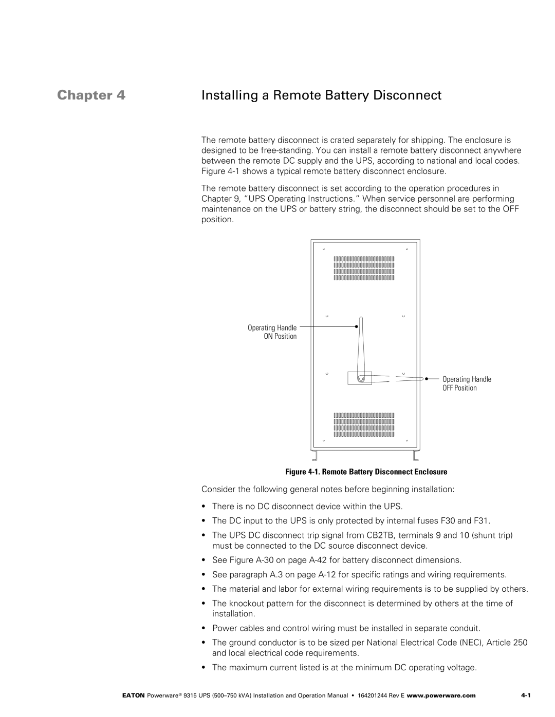
The remote battery disconnect is crated separately for shipping. The enclosure is designed to be free‐standing. You can install a remote battery disconnect anywhere between the remote DC supply and the UPS, according to national and local codes. Figure 4‐1 shows a typical remote battery disconnect enclosure.
The remote battery disconnect is set according to the operation procedures in Chapter 9, “UPS Operating Instructions.” When service personnel are performing maintenance on the UPS or battery string, the disconnect should be set to the OFF position.
Operating Handle
ON Position
Operating Handle
OFF Position
Figure 4‐1. Remote Battery Disconnect Enclosure
Consider the following general notes before beginning installation:
SThere is no DC disconnect device within the UPS.
SThe DC input to the UPS is only protected by internal fuses F30 and F31.
SThe UPS DC disconnect trip signal from CB2TB, terminals 9 and 10 (shunt trip) must be connected to the DC source disconnect device.
SSee Figure A‐30 on page
SSee paragraph A.3 on page
SThe material and labor for external wiring requirements is to be supplied by others.
SThe knockout pattern for the disconnect is determined by others at the time of installation.
SPower cables and control wiring must be installed in separate conduit.
SThe ground conductor is to be sized per National Electrical Code (NEC), Article 250 and local electrical code requirements.
SThe maximum current listed is at the minimum DC operating voltage.
EATON Powerware® 9315 UPS |