INSTALLATION REFERENCE
A.4 Location of UPS Terminals
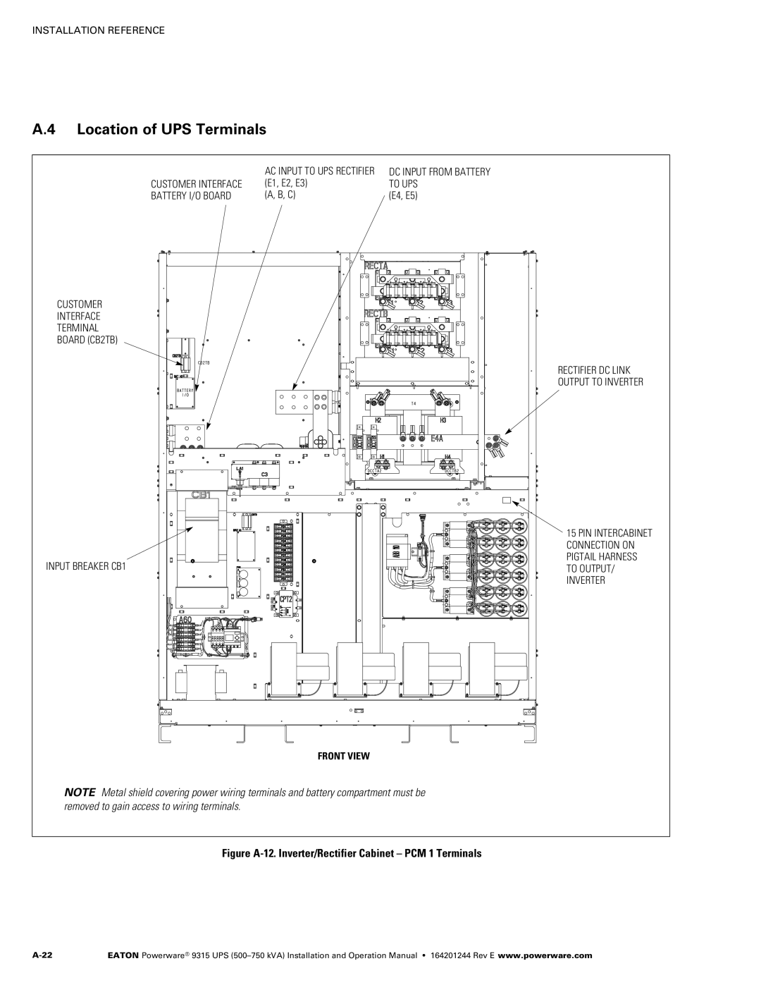
| AC INPUT TO UPS RECTIFIER | DC INPUT FROM BATTERY |
CUSTOMER INTERFACE | (E1, E2, E3) | TO UPS |
BATTERY I/O BOARD | (A, B, C) | (E4, E5) |
CUSTOMER
INTERFACE
TERMINAL
BOARD (CB2TB)
RECTIFIER DC LINK
OUTPUT TO INVERTER
INPUT BREAKER CB1
15 PIN INTERCABINET CONNECTION ON PIGTAIL HARNESS TO OUTPUT/ INVERTER
FRONT VIEW
NOTE Metal shield covering power wiring terminals and battery compartment must be removed to gain access to wiring terminals.
Figure A‐12. Inverter/Rectifier Cabinet – PCM 1 Terminals
EATON Powerware® 9315 UPS |