INSTALLATION REFERENCE
(See Section A.5) | AC INPUT TO UPS | |||||||
|
|
|
|
|
|
| ||
|
|
|
|
|
|
| RECTIFIER 3 WIRE | |
BATTERY/GENERATOR |
|
|
|
|
| |||
| ||||||||
INTERFACE |
|
|
|
|
| |||
|
|
|
| |||||
|
|
|
|
|
|
|
|
|
|
|
|
|
|
| A | ||
|
|
|
|
|
|
| ||
|
|
|
|
|
| |||
|
|
|
|
| ||||
|
|
|
|
|
|
|
| |
|
|
| CUSTOMER |
| INPUT/RECTIFIER | |||
|
|
| INTERFACE |
| PCM 1 | |||
|
|
|
|
| ||||
|
|
|
|
|
|
|
|
|
MIB (CB1) (OPTIONAL)
INPUT FILTER (OPTIONAL)
(See Section A.5)
|
| AC INPUT TO | |
| BUILDING ALARMS | BYPASS | |
| RELAY CONTACTS | 3 WIRE | |
|
| ||
| “ON INVERTER” | ROTATION | |
|
| ||
| “ON BYPASS” |
| |
| MONITORING | B | |
|
| ||
| REPO |
| |
|
| ||
CUSTOMER | OUTPUT/INVERTER |
| |
PCM 2 | PCM 3 | ||
INTERFACE | |||
|
|
DC LINK
INVERTER
INPUT
n
TRANSFORMER
n/ Y
RECTIFIER
C
DC LINK
BATTERY
FUSE
BATTERY BREAKER (OPTIONAL)
OUTPUT
TRANSFORMER
MOB (CB3)
n
Y
OUTPUT FILTER
CBP FBP
STATIC
SWITCH
BATTERY
STRING
D
AC OUTPUT TO CRITICAL LOAD
POWER CONTROL MODULE (PCM) | TO GROUND |
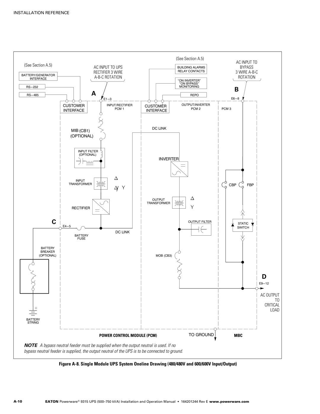
NOTE A bypass neutral feeder must be supplied when the output neutral is used. If no bypass neutral feeder is supplied, the output neutral of the UPS is to be connected to ground.
MBC
Figure A‐8. Single Module UPS System Oneline Drawing (480/480V and 600/600V Input/Output)
EATON Powerware® 9315 UPS |