USING THE CONTROL PANEL
8.1Using the LCD Screen
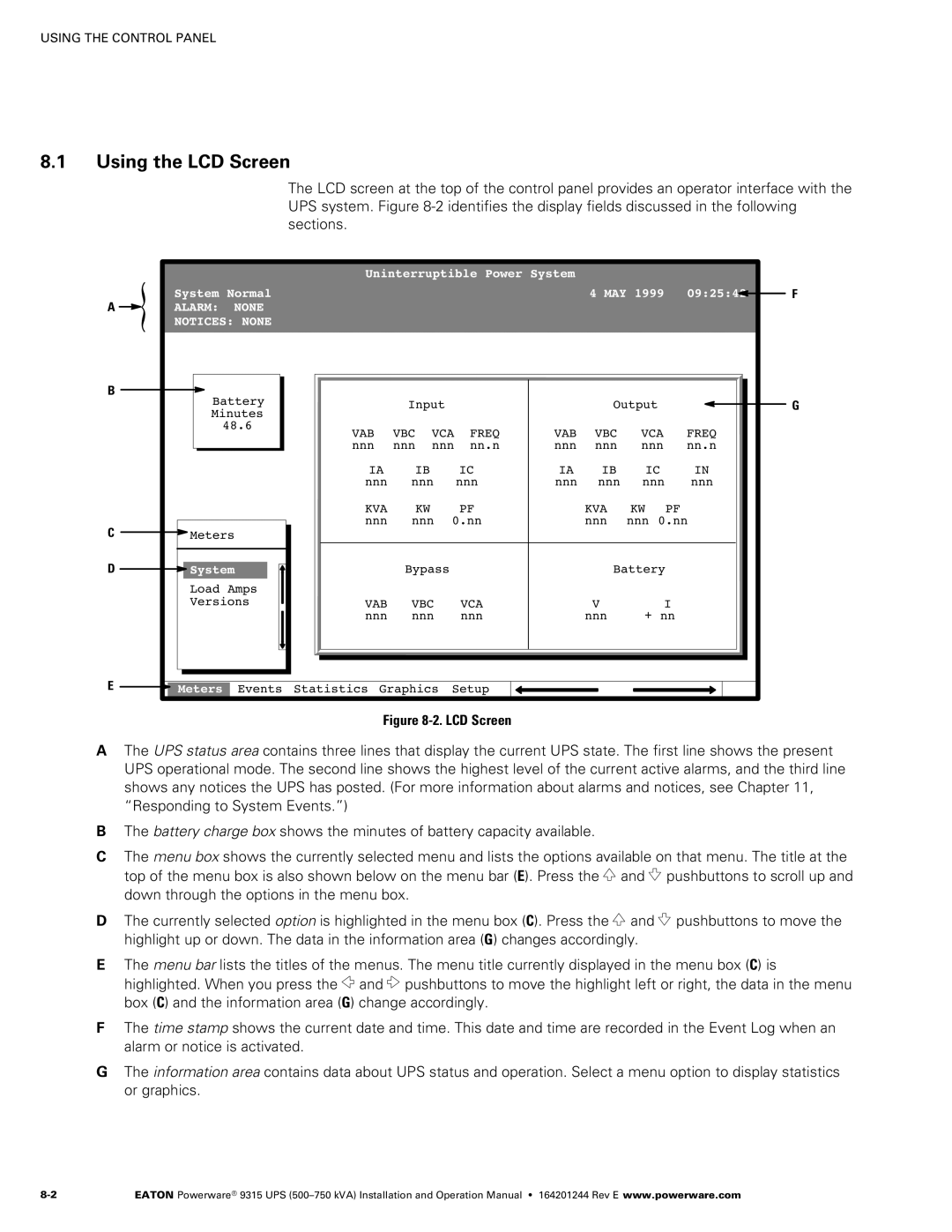
The LCD screen at the top of the control panel provides an operator interface with the UPS system. Figure 8‐2 identifies the display fields discussed in the following sections.
|
|
| Uninterruptible Power System |
|
|
|
| |||||
A | System Normal |
|
|
|
|
|
| 4 MAY 1999 | 09:25:42 | F | ||
ALARM: | NONE |
|
|
|
|
|
|
|
|
|
| |
| NOTICES: NONE |
|
|
|
|
|
|
|
|
|
| |
B | Battery |
|
|
|
|
|
|
|
|
|
| |
|
| Input |
|
|
| Output |
| G | ||||
| Minutes |
|
|
|
|
|
|
|
|
|
| |
| 48.6 | VAB | VBC | VCA | FREQ | VAB | VBC | VCA | FREQ |
| ||
|
|
|
| |||||||||
|
|
| nnn | nnn | nnn | nn.n | nnn | nnn | nnn | nn.n |
| |
|
|
| IA | IB |
|
| IC | IA | IB | IC | IN |
|
|
|
| nnn | nnn |
| nnn | nnn | nnn | nnn | nnn |
| |
|
|
| KVA | KW |
|
| PF |
| KVA | KW | PF |
|
C |
|
| nnn | nnn | 0.nn |
| nnn | nnn 0.nn |
| |||
Meters |
|
|
|
|
|
|
|
|
|
| ||
D | System |
| Bypass |
|
|
| Battery |
|
| |||
| Load Amps |
|
|
|
|
|
|
|
|
|
| |
| Versions | VAB | VBC |
| VCA |
| V | I |
| |||
|
|
| nnn | nnn |
| nnn |
| nnn | + nn |
| ||
E | Meters | Events | Statistics Graphics | Setup |
|
|
|
|
| |||
Figure 8‐2. LCD Screen
AThe UPS status area contains three lines that display the current UPS state. The first line shows the present UPS operational mode. The second line shows the highest level of the current active alarms, and the third line shows any notices the UPS has posted. (For more information about alarms and notices, see Chapter 11, “Responding to System Events.”)
BThe battery charge box shows the minutes of battery capacity available.
CThe menu box shows the currently selected menu and lists the options available on that menu. The title at the top of the menu box is also shown below on the menu bar (E). Press the ![]() and
and ![]() pushbuttons to scroll up and down through the options in the menu box.
pushbuttons to scroll up and down through the options in the menu box.
DThe currently selected option is highlighted in the menu box (C). Press the ![]() and
and ![]() pushbuttons to move the highlight up or down. The data in the information area (G) changes accordingly.
pushbuttons to move the highlight up or down. The data in the information area (G) changes accordingly.
EThe menu bar lists the titles of the menus. The menu title currently displayed in the menu box (C) is highlighted. When you press the ![]() and
and ![]() pushbuttons to move the highlight left or right, the data in the menu box (C) and the information area (G) change accordingly.
pushbuttons to move the highlight left or right, the data in the menu box (C) and the information area (G) change accordingly.
FThe time stamp shows the current date and time. This date and time are recorded in the Event Log when an alarm or notice is activated.
GThe information area contains data about UPS status and operation. Select a menu option to display statistics or graphics.
EATON Powerware® 9315 UPS |