INSTALLATION REFERENCE
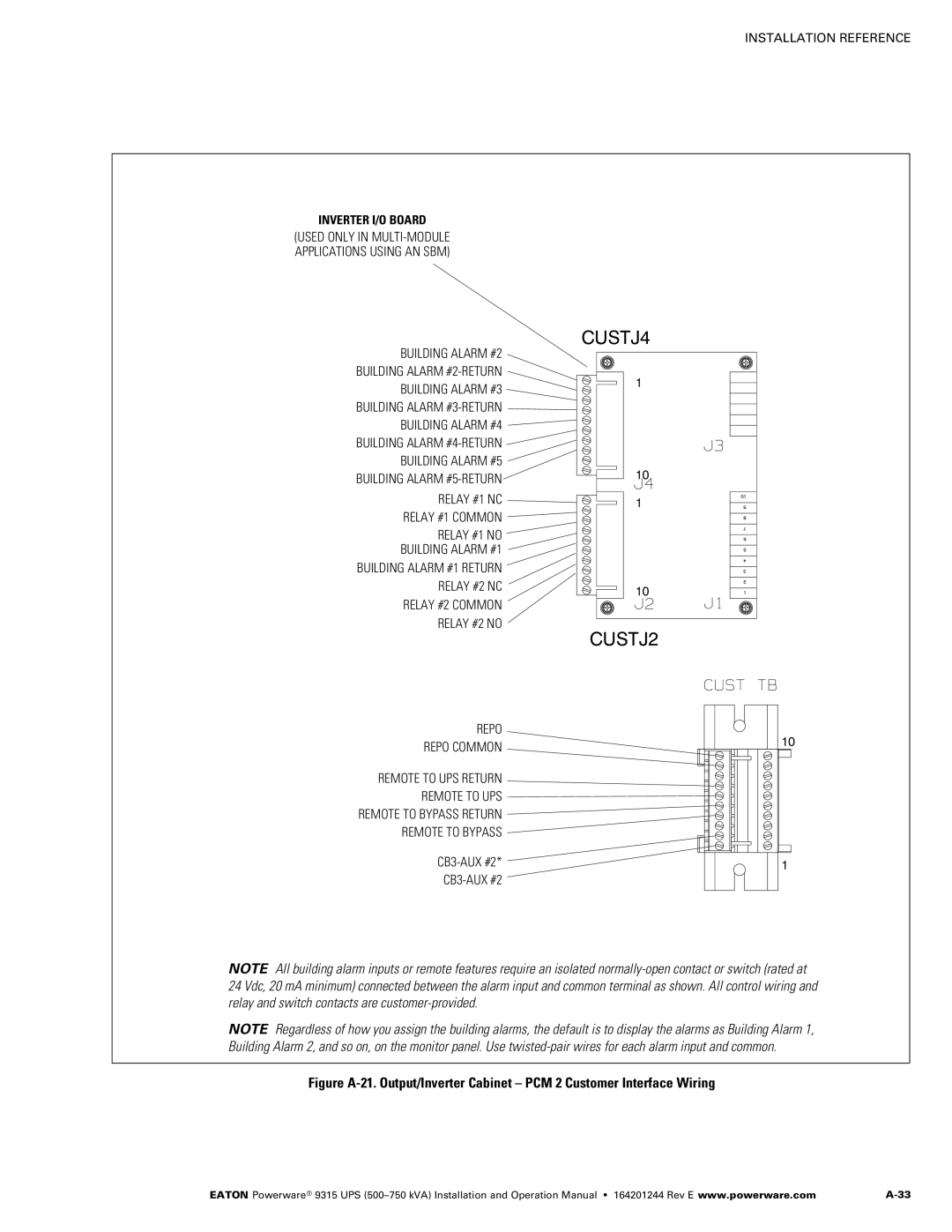
INVERTER I/O BOARD
(USED ONLY IN
CUSTJ4
BUILDING ALARM #2 |
| |
BUILDING ALARM | 1 | |
BUILDING ALARM #3 | ||
| ||
BUILDING ALARM |
| |
BUILDING ALARM #4 |
| |
BUILDING ALARM |
| |
BUILDING ALARM #5 |
| |
BUILDING ALARM | 10 | |
| ||
RELAY #1 NC | 1 | |
| ||
RELAY #1 COMMON |
| |
RELAY #1 NO |
| |
BUILDING ALARM #1 |
| |
BUILDING ALARM #1 RETURN |
| |
RELAY #2 NC | 10 | |
| ||
RELAY #2 COMMON |
| |
RELAY #2 NO |
|
CUSTJ2
REPO
REPO COMMON | 10 |
|
REMOTE TO UPS RETURN
REMOTE TO UPS
REMOTE TO BYPASS RETURN
REMOTE TO BYPASS
1 | |
|
NOTE All building alarm inputs or remote features require an isolated
NOTE Regardless of how you assign the building alarms, the default is to display the alarms as Building Alarm 1, Building Alarm 2, and so on, on the monitor panel. Use
Figure A‐21. Output/Inverter Cabinet – PCM 2 Customer Interface Wiring
EATON Powerware® 9315 UPS |