INSTALLATION REFERENCE
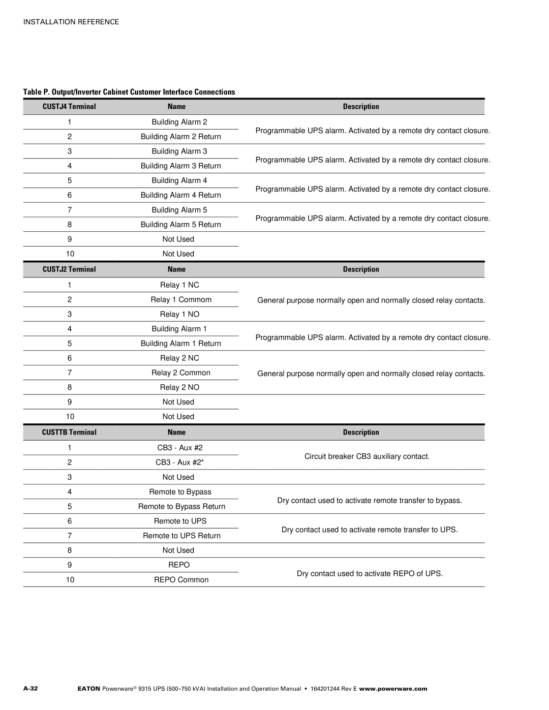
Table P. Output/Inverter Cabinet Customer Interface Connections
CUSTJ4 Terminal | Name | Description | |
|
|
| |
1 | Building Alarm 2 |
| |
|
| Programmable UPS alarm. Activated by a remote dry contact closure. | |
2 | Building Alarm 2 Return | ||
| |||
|
|
| |
3 | Building Alarm 3 |
| |
|
| Programmable UPS alarm. Activated by a remote dry contact closure. | |
4 | Building Alarm 3 Return | ||
| |||
|
|
| |
5 | Building Alarm 4 |
| |
|
| Programmable UPS alarm. Activated by a remote dry contact closure. | |
6 | Building Alarm 4 Return | ||
| |||
|
|
| |
7 | Building Alarm 5 |
| |
|
| Programmable UPS alarm. Activated by a remote dry contact closure. | |
8 | Building Alarm 5 Return | ||
| |||
|
|
| |
9 | Not Used |
| |
|
|
| |
10 | Not Used |
| |
|
|
|
CUSTJ2 Terminal | Name | Description | |
|
|
| |
1 | Relay 1 NC |
| |
|
|
| |
2 | Relay 1 Commom | General purpose normally‐open and normally‐closed relay contacts. | |
|
|
| |
3 | Relay 1 NO |
| |
|
|
| |
4 | Building Alarm 1 |
| |
|
| Programmable UPS alarm. Activated by a remote dry contact closure. | |
5 | Building Alarm 1 Return | ||
| |||
|
|
| |
6 | Relay 2 NC |
| |
|
|
| |
7 | Relay 2 Common | General purpose normally‐open and normally‐closed relay contacts. | |
|
|
| |
8 | Relay 2 NO |
| |
|
|
| |
9 | Not Used |
| |
|
|
| |
10 | Not Used |
| |
|
|
|
CUSTTB Terminal | Name | Description | |
|
|
| |
1 | CB3 - Aux #2 |
| |
|
| Circuit breaker CB3 auxiliary contact. | |
2 | CB3 - Aux #2* | ||
| |||
|
|
| |
3 | Not Used |
| |
|
|
| |
4 | Remote to Bypass |
| |
|
| Dry contact used to activate remote transfer to bypass. | |
5 | Remote to Bypass Return | ||
| |||
|
|
| |
6 | Remote to UPS |
| |
|
| Dry contact used to activate remote transfer to UPS. | |
7 | Remote to UPS Return | ||
| |||
|
|
| |
8 | Not Used |
| |
|
|
| |
9 | REPO |
| |
|
| Dry contact used to activate REPO of UPS. | |
10 | REPO Common | ||
| |||
|
|
|
EATON Powerware® 9315 UPS |