USING THE CONTROL PANEL
8.4Reading the Status Indicators
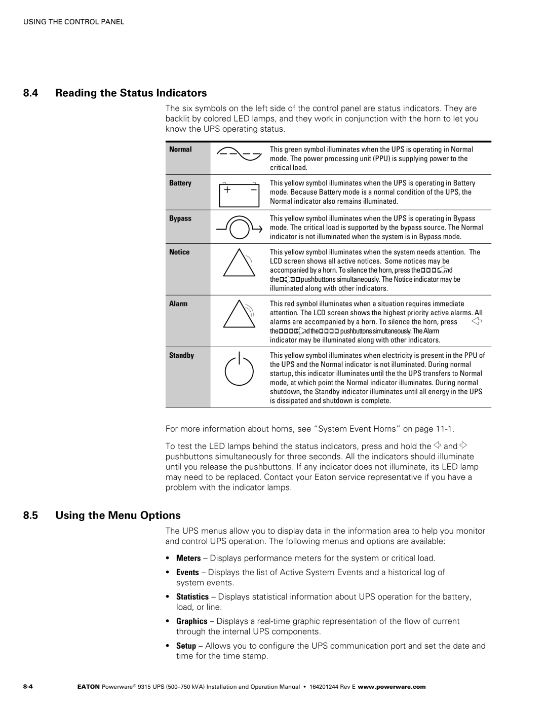
The six symbols on the left side of the control panel are status indicators. They are backlit by colored LED lamps, and they work in conjunction with the horn to let you know the UPS operating status.
Normal
Battery
Bypass
Notice
Alarm
Standby
This green symbol illuminates when the UPS is operating in Normal mode. The power processing unit (PPU) is supplying power to the critical load.
This yellow symbol illuminates when the UPS is operating in Battery mode. Because Battery mode is a normal condition of the UPS, the Normal indicator also remains illuminated.
This yellow symbol illuminates when the UPS is operating in Bypass mode. The critical load is supported by the bypass source. The Normal indicator is not illuminated when the system is in Bypass mode.
This yellow symbol illuminates when the system needs attention. The LCD screen shows all active notices. Some notices may be accompanied by a horn. To silence the horn, press the and the pushbuttons simultaneously. The Notice indicator may be illuminated along with other indicators.
This red symbol illuminates when a situation requires immediate attention. The LCD screen shows the highest priority active alarms. All alarms are accompanied by a horn. To silence the horn, press ![]() the andthe pushbuttonssimultaneously.TheAlarm
the andthe pushbuttonssimultaneously.TheAlarm
indicator may be illuminated along with other indicators.
This yellow symbol illuminates when electricity is present in the PPU of the UPS and the Normal indicator is not illuminated. During normal startup, this indicator illuminates until the the UPS transfers to Normal mode, at which point the Normal indicator illuminates. During normal shutdown, the Standby indicator illuminates until all energy in the UPS is dissipated and shutdown is complete.
For more information about horns, see “System Event Horns” on page
To test the LED lamps behind the status indicators, press and hold the ![]() and
and ![]() pushbuttons simultaneously for three seconds. All the indicators should illuminate until you release the pushbuttons. If any indicator does not illuminate, its LED lamp may need to be replaced. Contact your Eaton service representative if you have a problem with the indicator lamps.
pushbuttons simultaneously for three seconds. All the indicators should illuminate until you release the pushbuttons. If any indicator does not illuminate, its LED lamp may need to be replaced. Contact your Eaton service representative if you have a problem with the indicator lamps.
8.5Using the Menu Options
The UPS menus allow you to display data in the information area to help you monitor and control UPS operation. The following menus and options are available:
SMeters – Displays performance meters for the system or critical load.
SEvents – Displays the list of Active System Events and a historical log of system events.
SStatistics – Displays statistical information about UPS operation for the battery, load, or line.
SGraphics – Displays a real‐time graphic representation of the flow of current through the internal UPS components.
SSetup – Allows you to configure the UPS communication port and set the date and time for the time stamp.
EATON Powerware® 9315 UPS |