INSTALLING OPTIONAL ACCESSORIES
6.2Installing an RIM
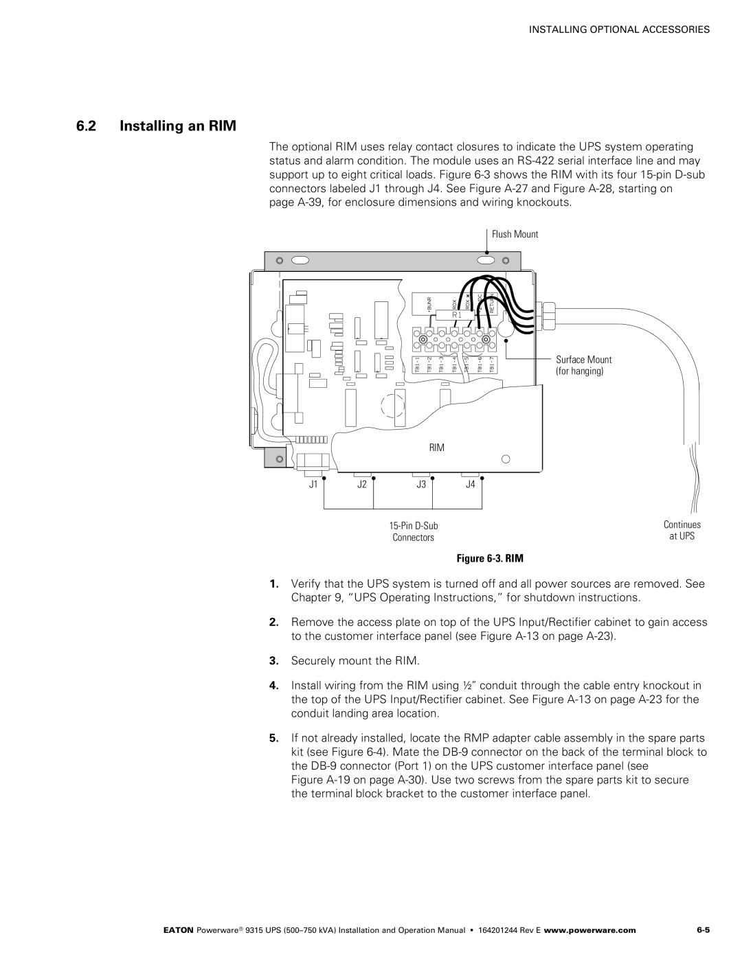
The optional RIM uses relay contact closures to indicate the UPS system operating status and alarm condition. The module uses an RS‐422 serial interface line and may support up to eight critical loads. Figure 6‐3 shows the RIM with its four 15‐pin D‐sub connectors labeled J1 through J4. See Figure A‐27 and Figure A‐28, starting on page
Flush Mount
|
| RIM |
|
J1 | J2 | J3 | J4 |
|
| 15‐Pin D‐Sub |
|
|
| Connectors |
|
Figure 6‐3. RIM
Surface Mount (for hanging)
Continues
at UPS
1.Verify that the UPS system is turned off and all power sources are removed. See Chapter 9, “UPS Operating Instructions,” for shutdown instructions.
2.Remove the access plate on top of the UPS Input/Rectifier cabinet to gain access to the customer interface panel (see Figure A‐13 on page
3.Securely mount the RIM.
4.Install wiring from the RIM using ½” conduit through the cable entry knockout in the top of the UPS Input/Rectifier cabinet. See Figure A‐13 on page
5.If not already installed, locate the RMP adapter cable assembly in the spare parts kit (see Figure 6‐4). Mate the DB‐9 connector on the back of the terminal block to the DB‐9 connector (Port 1) on the UPS customer interface panel (see
Figure A‐19 on page A-30). Use two screws from the spare parts kit to secure the terminal block bracket to the customer interface panel.
EATON Powerware® 9315 UPS |