Chapter 5 | Installing a Remote Emergency |
A
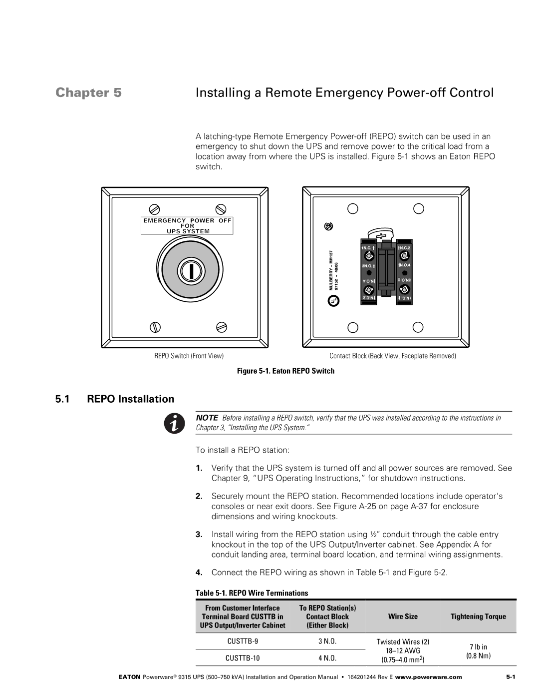
REPO Switch (Front View) | Contact Block (Back View, Faceplate Removed) |
Figure 5‐1. Eaton REPO Switch
5.1REPO Installation
NOTE Before installing a REPO switch, verify that the UPS was installed according to the instructions in
Chapter 3, “Installing the UPS System.”
To install a REPO station:
1.Verify that the UPS system is turned off and all power sources are removed. See Chapter 9, “UPS Operating Instructions,” for shutdown instructions.
2.Securely mount the REPO station. Recommended locations include operator's consoles or near exit doors. See Figure A‐25 on page
3.Install wiring from the REPO station using ½” conduit through the cable entry knockout in the top of the UPS Output/Inverter cabinet. See Appendix A for conduit landing area, terminal board location, and terminal wiring assignments.
4.Connect the REPO wiring as shown in Table 5‐1 and Figure 5‐2.
Table 5‐1. REPO Wire Terminations
From Customer Interface | To REPO Station(s) | Wire Size | Tightening Torque | |
Terminal Board CUSTTB in | Contact Block | |||
UPS Output/Inverter Cabinet | (Either Block) |
|
| |
|
|
|
| |
CUSTTB‐9 | 3 N.O. | Twisted Wires (2) | 7 lb in | |
|
| |||
CUSTTB‐10 | 4 N.O. | (0.8 Nm) | ||
|
EATON Powerware® 9315 UPS |