Digital Video Recorder with Multiplexer Function
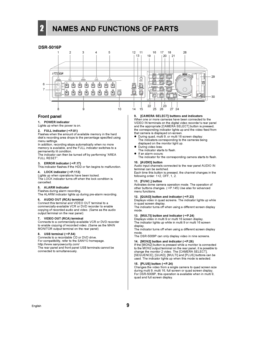
About this manual
Location
Precaution
Service
Avoiding Electrical Shock and Fire
Symbols used in this manual
Main features
Accessories
Introduction
Contents
Contents Settings
Network Control
Contents Network Operation
Network Settings
Contents Other
Important recordings
Before USE
HDD and cooling fan are consumable components
Protection of the HDD
Backup battery
Before USE
DSR-5016P
Names and Functions of Parts
Front panel
Names and Functions of Parts
DSR-5009P
Rear panel
AC power socket AC
Sensor Alarm OUT terminals
ALL Reset button
Power cord holder
Basic connections DSR-5016P
Installation and Connections
Connecting the RS-232C terminal
RS-232C Pin locations
Installation and Connections
Connecting RS-485 control terminals
Connect as above
Connecting to a 2ND RS485/422 terminal
RS-485 termination switch settings
Operation
Connecting alarm input terminals
Connecting a LAN terminal
Connecting an amplifier
LAN connection
Connecting the power cord
Connecting Sensor Alarm OUT terminals
Connecting control terminals
Operation
Preparing for USE
01-01-05 000000 REC Repeat EN a Alarm
Operation display
Changing the language
Preparing for USE
Changing the display position of the operation display area
Press the EXIT/OSD button
Example Setting 830 on 26 October
Setting the time
Turn the shuttle dial clockwise
Recording area
Hard disk archive area
Hard disk recording areas
Archive area
Press the No Camera Select button
Monitoring Video from a Camera
Viewing on a full screen
Press the Zoom button during monitoring of camera video
Press the Zoom button to return to normal magnification
Monitoring Video from a Camera
Viewing on quad screens
Press the Quad button
Press the Multi button
Viewing on multi 9 or multi 16 screens
Enlarging video
Press the Plus button during multi 9 screen display
Automatic camera selection
Setting automatic full screen selection
Setting automatic quad-screen selection
Press the Sequence button
Viewing on a quad screen
Viewing on monitor
Press the MON2 button
Viewing on a full screen
Viewing on multi 9 or multi 16 screens
Monitor Main monitor
MON2 indicator turns off
Displaying alarm video in full screen format
Monitor
Recording
Timer recording
Set timer recording. JP.87 Press the Timer button
Normal recording
Pre-alarm recording
Alarm recording
Recording
Fast-forward and fast-rewind playback
Play
Playing video on a full screen
Changing the playback speed
Magnifying the playback video
Play
Press the Zoom button during playback
Frame advance forward/reverse
Viewing still images
Playing video on multiple screens
Screens
To view video from other cameras
Video on full, quad, multi 9 or multi
Press the Multi button during Playback
Searching for Recorded Video
Motion Detection Search JP.45
Searching for Recorded Video
Alarm log search
„ To confirm normal recording
DATE/TIME
Alarm search
Total Alarms
Search
Search screen, press the FUNC. button and select Search
Entering an alarm number to search for an alarm video
„ To view pre-alarm video
Search input field flashes
Cursor moves to the list
Entering a camera number to search for an alarm video
Press the FUNC. button
Channel input field flashes
Press the Alarm button during playback
Alarm thumbnail search
To view alarm video before or after the current playback
Turn the jog dial to select the video for playback
Search by entering an alarm number
Search screen, press the FUNC. button
Recording TOP
Time/date search
Search by entering a camera number
Recording END
Press the Camera Select 5 button
Turn the shuttle dial clockwise while Channel is selected
Specify the date and time
Start
Searching within the archive area
Date
Total
Cursor moves to Search
Entering an archive number to search for an alarm video
Motion detection search
Motion Detection Search screen is displayed
END
Setting the motion sensor for searching
Start
Motion Sensor
‹OFF
Viewing video detected by the motion sensor
Turn the jog dial to select Preview
„ If not FOUND! is displayed
Set the motion sensor again
Copying video to a CompactFlash card or Microdrive JP.51
Saving Copying Recorded Video
Copying video to the hard disk’s archive area JP.50
Copying video to a CD-R/RW or DVD+R/+RW JP.54
Press the Copy button
Saving Copying Recorded Video
Copying video to the hard disk’s archive area
Set the time
Insert a CompactFlash card
„ To cancel copying
Copying to a CompactFlash card or Microdrive
Example Copying 20 images
Turn the shuttle dial clockwise while Pictures is flashing
Maximum
Viewing images copied to a CompactFlash card on a PC
Available space and write capacity are checked
Connect a recordable CD or DVD drive and insert a disk
Copying to a CD-R/RW or DVD+R/ +RW
Example Copying the maximum video to the copy destination
Number of images flashes
Cursor appears on Copy Start
‹COMPACT
Formatting a CompactFlash card, CD-RW or
Flash Disc Writer
Viewing images on a PC
Dcim Viewer YYMMDD99
Turn the jog dial to select an item
Menu Configuration and Operations
Basic menu operations
Turn the jog dial to select a function
Movement and confirmation in sub-menus and setting screens
Menu Configuration and Operations
Resetting menu items
Displayed settings are restored to their default values
Copy Menu Settings JP.135 Stores and loads menu
Sub-menu configuration
Power LOSS/USED Time JP.133 Displays the date and time
Advanced Menu SET JP.138 Sets the ROI setting, alarm
Configuration
Initial SET
Turn the jog dial to select Mode under Summer Time SET
Setting the language
Setting the summer time
Initial SET
Summer time begins
External clock setting
Set the date and time
Summer time ends
Detecting connected cameras
Flashes Default setting is
Example Set to
Example Setting the title HALL-1STFL for Camera No
Setting camera titles
Quad
Holiday SET screen is displayed Default setting is
Setting holidays
Example Setting 26 October as a holiday
Turn the jog dial to select H
Setting time periods
Set the day and month for item
„ Alarm recording using motion sensors
„ Setting automatic selection of camera video
„ Masking camera video using a gray pattern
Operations during the specified time periods
Set the time for T-1
Timer period settings
Example 1 Setting periods using Time Period a
Set the time for T-2
Time Period a flashes
Timer period operations settings
Cursor moves to Time Period a
Record SET
Alarm Operation SET JP.102 Makes settings for
Normal recording easy setup
Setting based on recording days
Record SET
Set the time for timer recording
Example Timer recording from 8 AM to 8 PM
Turn the shuttle dial counter-clockwise
Setting based on recording rate
Example on
REC Rate Base
25 FPS/CAM
Displays the total capacity of the hard disk
Displaying the recording areas
Recording Area SET screen is displayed
Hard disk capacity
Changing recording areas
„ Default hard disk settings
Example Setting the recording area to 50%
Turn the jog dial to select YES
Setting overwrite permission
Recordings can now be made to the recording area
OFF
Setting recording conditions
‹ON
‹MANUAL Copy
01-01-05 000000 REC 5% EN a Alarm
Auto Alarm
Copy
Setting auto deleting
Setting normal recording
FPS flashes
„ Setting the picture quality for each camera
Default setting OFF
Allowable
Program
Setting program recording
Example P-1
Select Individual Camera Rate
Cursor moves to 01 under Select Individual Camera Rate FPS
Program REC SET screen is displayed
Flashes for Program
Recording rate is not set
Timer settings
Timer setting items
OFF flashes for SET
Setting the Start and Stop time
Indicating the hour from Start flashes
Cursor appears in the bottom line
To cancel all set timer reservations
Use the same procedure to set other items
„ To change a setting item
EXT
SAT in the Week column flashes
Make settings in the Week and Start columns
Timer recordings spanning more than 24 hours
Line
Timer recording using an external timer
OFF 5FPS
Setting timer recording
Cursor moves to line
Setting alarm recording
To set alarm recording
Cursor moves to Alarm Interleave
Only flashes
‹ONLY
Cursor moves to PRE-ALARM Recording
To set pre-alarm recording
Number of alarms Alarm display
Flashes Default setting 12.5FPS
Pre-alarm recording is disabled
Pre-alarm recording is enabled
Cursor moves to Alarm Trigger
Use this setting to indicate how alarms are to be detected
Setting alarm triggers
Number of alarms
PRE display
Setting the motion sensors
Level
Turn the jog dial to select a or B
Use the same procedure to set other sensor positions
100
Turn the shuttle dial clockwise twice
Setting sensor modes
Setting time periods
Setting sensitivity levels
101
„ To stop motion sensor recording
Setting alarm operation and display
102
To B
103
104
Canceling an alarm
105
106
RS-232C/RS-485 SET JP.115 Makes settings when
General SET
HDD SET JP.117
107
Setting data display
General SET
108
Setting display for video loss
On flashes for Video Loss
Setting the buzzer
109
Setting the security lock
110
Change
111
‹NORMAL
LV4
„ User level and privileges
Setting user ID
112
Registering a user
113
Enter a password
Turning on the key lock, password lock and network lock
Enter a user ID
114
During password lock, press
Enter the user ID and password
Confirm the lock status
RS-232C/RS-485 SET screen is displayed
Setting RS-232C and RS-485
115
RS-485 flashes
116
Hard disk initialization and mirroring
Setting mirroring
117
Initializing the hard disk
118
‹MASTER
119
Switching playback disks
Expanding Replacing and initializing the hard disk
Switch
Network settings
Making network settings
120
Set Subnet Mask
121
Set IP Address
Set Gateway
122
Set Http Port
Making network control settings
123
124
„ User levels and privileges
Setting user
125
LV1 LV2 LV3 LV4
Screen SET
Setting quad and multi 9/16 display
126
Screen SET
127
Checking modified screen positions
1S flashes for Full
128
Screen SET screen is displayed
Automatic selection is set to an interval of 5 seconds
Flash for Time Period
129
MAIN/MON.2 Monitor SET screen is displayed
Cursor moves to 1S for 01 and Main MON
130
Setting masks
‹ 1S 30S Switching interval seconds
Channel not displayed
Use the same procedure to set other channels
131
132
Setting the color level
Settings The default setting is
Color Level SET screen is displayed
133
Power LOSS/USED Time
Select Used Time and then turn the shuttle dial clockwise
Area
Initialization LOG
134
Action
Copy Menu Settings screen is displayed Jog dial
Copy Menu Settings
Saving menu settings
135
Copy Menu Settings screen is displayed
Copy Menu Settings
Loading menu settings
136
137
Copying the recording area settings
Use the following procedure to copy recording area settings
Cursor appears on Save Menus to CF
Advanced Menu SET
138
139
Setting ROI
Setting the ROI
Advanced Menu SET
140
Set Time LAG to OFF when Level is set English
Response sensitivity is disabled
Response sensitivity is enabled. Lower
141
No operation after the response-stop
Setting ROI areas
142
1S 10S
Cursor moves to the bottom right
143
Set the areas in frame 2 and frame 3 in the same way
Cursor the orange † moves to the top left of frame
Setting alarm notification
144
Sanyo COAX1 Sanyo Coax Sanyo RS485 BBV Coax Pelco Coax
Camera control settings
145
Sanyo COAX2
146
Click the buttons to operate the camera
Making PPP settings
147
Operating the camera with the digital video recorder
148
Time Zone SET / NTP SET screen is displayed
Time zone/NTP setting
149
GMT Dublin, Lisbon, London flashes
Set Time to Synchronize
150
Set NTP Server Address
Example
Page
Manual for Remote Operation by Network Connection
153
Digital video recorder network settings
Getting Prepared
Operations possible with PC control
Click the Security tab
154
Getting Prepared
Click Custom Level
Click Properties
155
Click Network Connections
Click OK
156
Network Control
Controlling from a PC
157
Disconnecting
Messages displayed when connected
Select a language and click OK
„ When network settings are changed
„ When control rights are switched to the unit
Display on the PC „ When disconnected from the network
158
159
Operation panel
Operation Panel Functions and Restrictions
160
Camera operation panel
161
Finishing dome camera operation
Click the button on the operation panel
Recording Images
162
Stopping normal recording
163
Watching Images
Various ways of displaying live images
164
Performing operations in play mode
Watching Images
Adjusting the image and audio
165
166
Normal Recording Mode
Alarm Recording Mode
Screen display items
167
Downloading live images to a PC
„ To cancel a save operation
When saving is completed, click OK on the pop-up window
168
Basic operation
Search for video using the search mode screen
169
Search menu
Searching for Recorded Video Alarm LOG Search
170
Alarm Thumbnail Search
Searching for Recorded Video Alarm Search
171
Archive Area Search
172
Searching for Recorded Video TIME/DATE Search
Click 4. TIME/DATE Search on the Search screen
Click 6. Motion Detection Search on the Search screen
173
Searching for Recorded Video Motion Detection Search
Specify the search area from the Search from pull-down menu
Click Button on the operation Panel
174
Copying to the archive area
Enter the number of images for HOW Many
175
Downloading to a PC
176
Displays the download results
Making menu selections
Settings
177
Click a menu on the Main Menu
178
Menu structure
Clock SET
179
Summer Time SET/EXT. Clock SET
Click Save
180
Holiday SET
Click 3. Holiday SET
Click 2. Record SET
181
Recording Area SET
Click 1. Recording Area SET
182
Recording Conditions SET
Record SET Normal REC Mode SET
183
Set REC Program Group to the desired program group
184
Program REC SET
Click 4. Program REC SET
Click 5. Timer SET
Record SET Timer SET
185
Set Alarm Recording to the desired recording mode
Record SET Alarm REC Mode SET
Click 6. Alarm REC Mode SET
Setting alarm recording
Set PRE-ALARM Recording to on or OFF
Set Alarm Interleave to the desired recording pattern
Set Duration to the desired alarm recording duration
187
188
Set Duration to the desired pre- alarm recording duration
Alarm or
15MIN
Display SET
189
Buzzer SET
Security Lock SET
To cancel the buzzer setting on the PC
190
Click 3. Security Lock SET
191
Set user ID for User ID Set Password Set user level for LV
Settings Description Level
General SET User ID SET
HDD SET
192
RS-232C/RS-485 SET
Click 5. RS-232C/RS-485 SET
Network SET
Change the settings as required
193
Click 7. Network SET
Click 8. Network Control SET
194
Network Control SET
Set Network Status to on or OFF
195
196
Sequence SET
Click 2. Mask SET
197
Screen SET Mask SET
Set the following functions as required
Click 5. Power LOSS/USED Time
Power LOSS/USED Time
198
Initialization LOG
199
Click 6. Initialization LOG
Click 7. Copy Menu Settings
Saving Menu Settings
Loading Menu Settings
200
Set Alarm Notice to on
Alarm Notice SET
Click 1. Alarm Notice SET
201
PPP SET
202
Camera Control SET
Click 2. Camera Control SET
203
NTP SET
Click 4. Time ZONE/NTP SET
Setting is saved Click Renewal to manually update the time
204
Set Time Zone
205
Installing DVR Viewer2
DVR VIEWER2
Operating environment
Opening and closing DVR Viewer2
206
DVR VIEWER2
Opening DVR Viewer2
Click OpenO on the FileF menu
207
Opening files
Click Browse... to display the folder tree
Main window
208
Viewing images
Thumbnail window
Prev
209
TOP
Rplay
210
Printing images
RS-232C specifications
Interface Specifications
RS-485 specifications
211
DVR/VCR command table
Interface Specifications
212
213
Specifications
Jpeg
Units mm
Specifications Dimensions
214
420
Specifications Table of recording rates and times
215
216
217
Specifications Table of recording rate settings
Recording rates that cannot be selected English
Specifications Table of pre-alarm recording times
218
Specifications Terminal board specifications
219
220
Record SET →P.71
Menu Setting Sequence
221
Recording Area SET →P.77
222
Menu Setting Sequence
Power LOSS/USED Time → P.133
Network SET →P.120
Initialization LOG →P.134
Alarm Notice SET →P.144
223
Dial UP SET →P.148
Index
Symbols
224
Index
225
112, 125
L8HBD/XE, L8HBF/XE 0405TR-SY