4 Replacement Procedures 4.28 TFT FL (Model 14.1 XGA LG. Philips
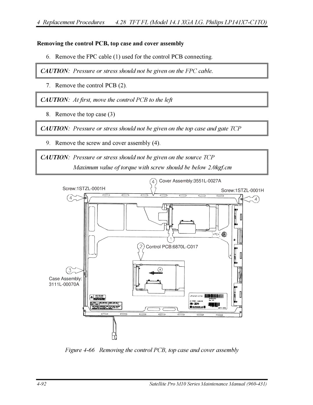
Removing the control PCB, top case and cover assembly
6. Remove the FPC cable (1) used for the control PCB connecting.
CAUTION: Pressure or stress should not be given on the FPC cable.
7. Remove the control PCB (2).
CAUTION: At first, move the control PCB to the left
8. Remove the top case (3)
CAUTION: Pressure or stress should not be given on the top case and gate TCP
9. Remove the screw and cover assembly (4).
CAUTION: Pressure or stress should not be given on the source TCP Maximum value of torque with screw should be below 2.0kgf.cm
| Cover | ||
|
| ||
|
|
| |
|
|
|
|
|
|
|
|
Control
Case Assembly:
Figure 4-66 Removing the control PCB, top case and cover assembly
Satellite Pro M10 Series Maintenance Manual |
