2.3 Power Supply Troubleshooting | 2 Troubleshooting Procedures |
Procedure 3 Connection Check
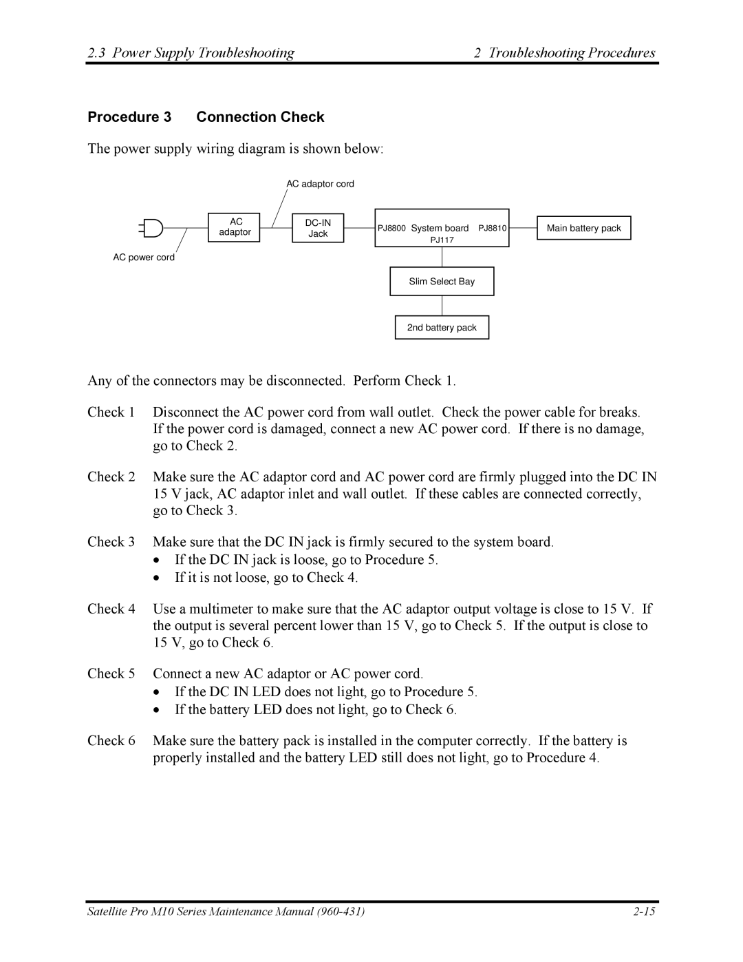
The power supply wiring diagram is shown below:
|
| AC adaptor cord |
|
| |||||
|
|
|
|
|
|
|
|
| |
|
|
|
|
|
|
|
|
|
|
AC |
|
|
|
| PJ8800 | System board PJ8810 | |||
adaptor |
|
|
| Jack | |||||
|
|
|
|
| |||||
PJ117
AC power cord
Slim Select Bay
2nd battery pack
Any of the connectors may be disconnected. Perform Check 1.
Main battery pack
Check 1 Disconnect the AC power cord from wall outlet. Check the power cable for breaks. If the power cord is damaged, connect a new AC power cord. If there is no damage, go to Check 2.
Check 2 Make sure the AC adaptor cord and AC power cord are firmly plugged into the DC IN 15 V jack, AC adaptor inlet and wall outlet. If these cables are connected correctly, go to Check 3.
Check 3 Make sure that the DC IN jack is firmly secured to the system board.
•If the DC IN jack is loose, go to Procedure 5.
•If it is not loose, go to Check 4.
Check 4 Use a multimeter to make sure that the AC adaptor output voltage is close to 15 V. If the output is several percent lower than 15 V, go to Check 5. If the output is close to 15 V, go to Check 6.
Check 5 Connect a new AC adaptor or AC power cord.
•If the DC IN LED does not light, go to Procedure 5.
•If the battery LED does not light, go to Check 6.
Check 6 Make sure the battery pack is installed in the computer correctly. If the battery is properly installed and the battery LED still does not light, go to Procedure 4.
Satellite Pro M10 Series Maintenance Manual |