2 Troubleshooting Procedures | 2.12 Sound Troubleshooting |
Procedure 2 Connector Check
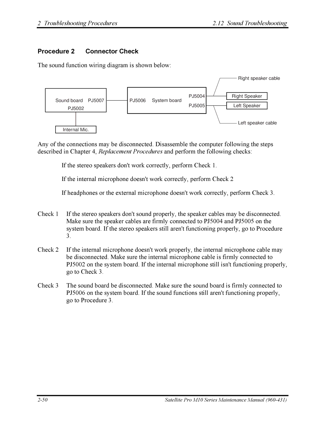
The sound function wiring diagram is shown below:
PJ5004
Sound board PJ5007 |
| PJ5006 System board |
|
Right speaker cable
Right Speaker
PJ5002
PJ5005
Left Speaker
Left speaker cable
Internal Mic.
Any of the connections may be disconnected. Disassemble the computer following the steps described in Chapter 4, Replacement Procedures and perform the following checks:
If the stereo speakers don't work correctly, perform Check 1.
If the internal microphone doesn't work correctly, perform Check 2
If headphones or the external microphone doesn't work correctly, perform Check 3.
Check 1 If the stereo speakers don't sound properly, the speaker cables may be disconnected. Make sure the speaker cables are firmly connected to PJ5004 and PJ5005 on the system board. If the stereo speakers still aren't functioning properly, go to Procedure 3.
Check 2 If the internal microphone doesn't work properly, the internal microphone cable may be disconnected. Make sure the internal microphone cable is firmly connected to PJ5002 on the system board. If the internal microphone still isn't functioning properly, go to Check 3.
Check 3 The sound board be disconnected. Make sure the sound board is firmly connected to PJ5006 on the system board. If the sound functions still aren't functioning properly, go to Procedure 3.
Satellite Pro M10 Series Maintenance Manual |