4 Replacement Procedures
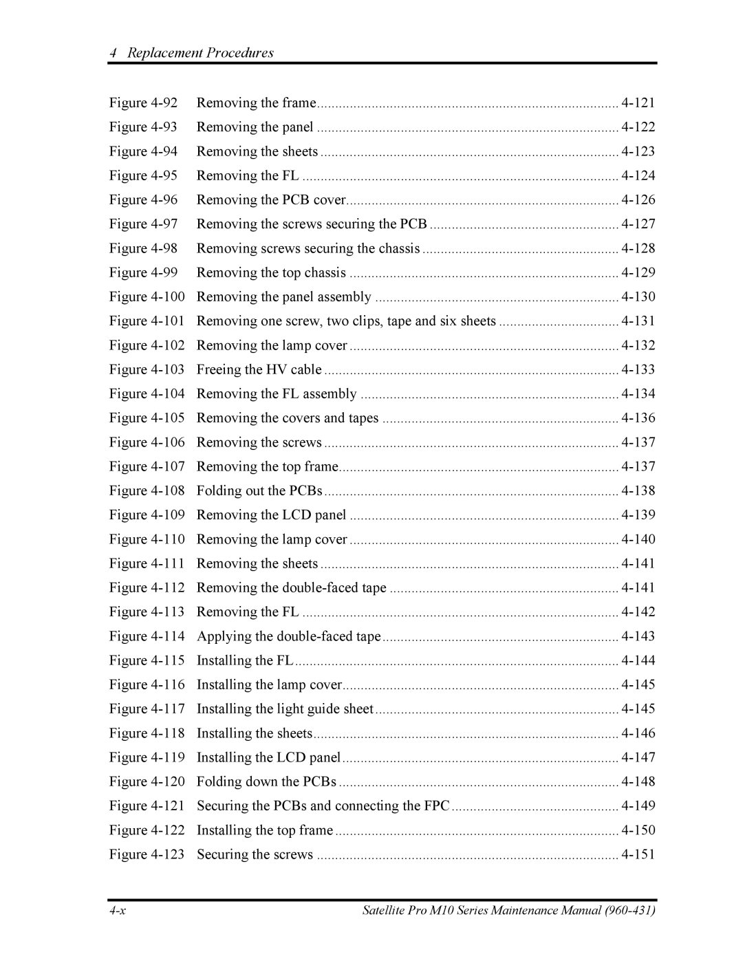
Figure | Removing the frame | |
Figure | Removing the panel | |
Figure | Removing the sheets | |
Figure | Removing the FL | |
Figure | Removing the PCB cover | |
Figure | Removing the screws securing the PCB | |
Figure | Removing screws securing the chassis | |
Figure | Removing the top chassis | |
Figure | Removing the panel assembly | |
Figure | Removing one screw, two clips, tape and six sheets | |
Figure | Removing the lamp cover | |
Figure | Freeing the HV cable | |
Figure | Removing the FL assembly | |
Figure | Removing the covers and tapes | |
Figure | Removing the screws | |
Figure | Removing the top frame | |
Figure | Folding out the PCBs | |
Figure | Removing the LCD panel | |
Figure | Removing the lamp cover | |
Figure | Removing the sheets | |
Figure | Removing the | |
Figure | Removing the FL | |
Figure | Applying the | |
Figure | Installing the FL | |
Figure |
| |
Figure |
| |
Figure |
| |
Figure | Installing the LCD panel |
|
Figure | Folding down the PCBs |
|
Figure | Securing the PCBs and connecting the FPC |
|
Figure |
| |
Figure | Securing the screws |
|
Satellite Pro M10 Series Maintenance Manual |
