COURIER HIGH SPEED MODEMS
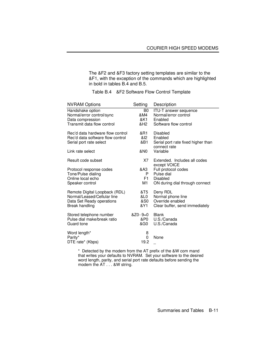
The &F2 and &F3 factory setting templates are similar to the &F1, with the exception of the commands which are highlighted in bold in tables B.4 and B.5.
Table B.4⎯&F2 Software Flow Control Template
NVRAM Options | Setting Description |
Handshake option Normal/error control/sync Data compression
Transmit data flow control
Rec'd data hardware flow control Rec'd data software flow control Serial port rate select
Link rate select
Result code subset
Protocol response codes
Tone/Pulse dialing
Online local echo
Speaker control
Remote Digital Loopback (RDL) Normal/Leased/Cellular line Data Set Ready operations Break handling
Stored telephone number Pulse dial make/break ratio Guard tone
Word length*
Parity*
DTE rate* (Kbps)
B0 | |
&M4 | Normal/error control |
&K1 | Enabled |
&H2 | Software flow control |
&R1 | Disabled |
&I2 | Enabled |
&B1 | Serial port rate fixed higher than |
| connect rate |
&N0 | Variable |
X7 | Extended. Includes all codes |
| except VOICE |
&A3 | Full protocol codes |
PPulse dial
F1 Disabled
M1 ON during dial through connect
&T5 | Deny RDL |
&L0 | Normal phone line |
&S0 | Override enabled |
&Y1 | Clear buffer, send immediately |
&Z0−9=0 | Blank |
&P0 | U.S./Canada |
&G0 | U.S./Canada |
8
0None
19.2_
*Detected by the modem from the AT prefix of the &W command that writes your defaults to NVRAM. Set your software to the desired word length, parity, and serial port rate defaults before sending the modem the AT . . . &W string.