COURIER HIGH SPEED MODEMS
Set DIP Switches
A
WARNING: Check your software documentation for its requirements, particularly for DIP switches 1, 4, 5 and 6.
NOTE: Once the modem is installed, the DIP switches are accessible through the computer's rear panel.
INSTALLING THE MODEM
1.Turn off the computer and peripheral devices.
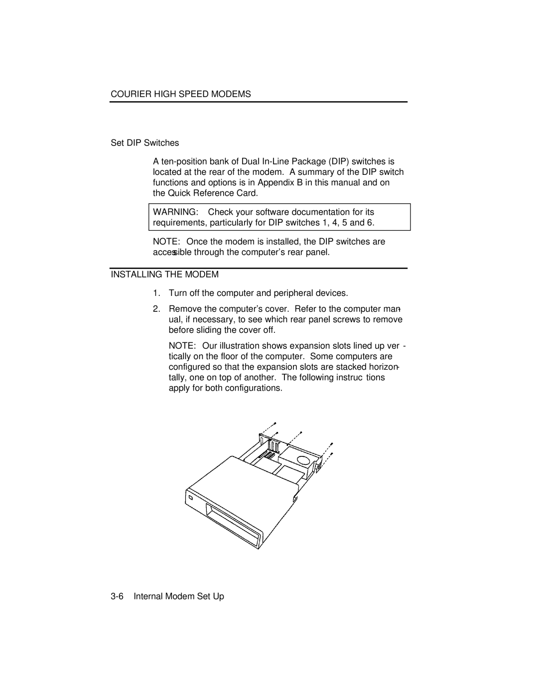
2.Remove the computer's cover. Refer to the computer man- ual, if necessary, to see which rear panel screws to remove before sliding the cover off.
NOTE: Our illustration shows expansion slots lined up ver- tically on the floor of the computer. Some computers are configured so that the expansion slots are stacked horizon- tally, one on top of another. The following instructions apply for both configurations.