COURIER HIGH SPEED MODEMS
6.Locate the voice/data switch at the front of the modem. Lift up and remove the modem (printed circuit board), carefully easing the voice/data switch out of its opening in the front panel.
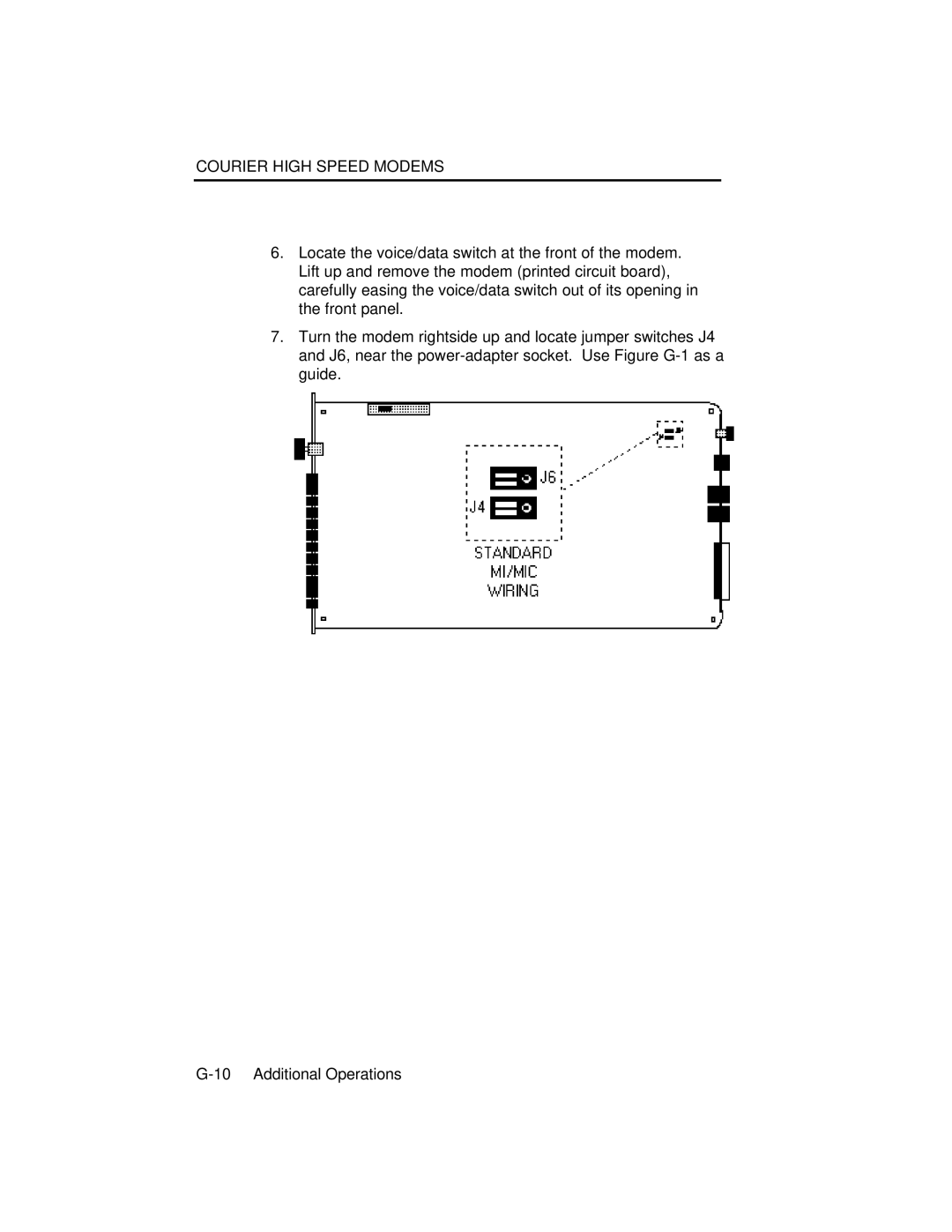
7.Turn the modem rightside up and locate jumper switches J4 and J6, near the
Figure G-1⎯Courier Modem Board
8.The jumpers are black shunts that cover two out of three upright metal contacts. As shown in the figure, set the jumpers so they cover the two contacts on each switch that are closest to the front panel. The third contact on each switch is exposed.
9.Replace the modem in the case top: ease the voice/data switch into the opening in the front panel and make sure the back of the board rests on the locator pins at the rear (from which you removed the screws).