COURIER HIGH SPEED MODEMS
PIN ASSIGNMENTS
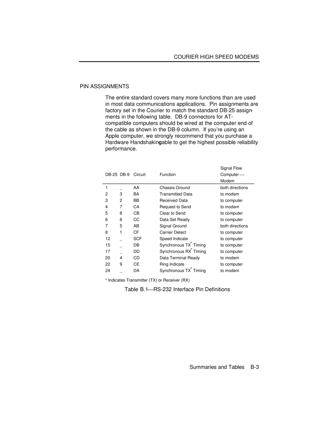
The entire standard covers many more functions than are used in most data communications applications. Pin assignments are factory set in the Courier to match the standard
|
|
|
| Signal Flow |
| Circuit | Function | Computer⎯ | |
|
|
|
| Modem |
1 | _ | AA | Chassis Ground | both directions |
2 | 3 | BA | Transmitted Data | to modem |
3 | 2 | BB | Received Data | to computer |
4 | 7 | CA | Request to Send | to modem |
5 | 8 | CB | Clear to Send | to computer |
6 | 6 | CC | Data Set Ready | to computer |
7 | 5 | AB | Signal Ground | both directions |
8 | 1 | CF | Carrier Detect | to computer |
12 | _ | SCF | Speed Indicate | to computer |
15 | _ | DB | Synchronous TX* Timing | to computer |
17 | _ | DD | Synchronous RX* Timing | to computer |
20 | 4 | CD | Data Terminal Ready | to modem |
22 | 9 | CE | Ring Indicate | to computer |
24 | _ | DA | Synchronous TX* Timing | to modem |
* Indicates Transmitter (TX) or Receiver (RX)
Table B.1⎯RS-232 Interface Pin Definitions
Summaries and Tables