COURIER HIGH SPEED MODEMS
3.Unscrew the solid bracket at the back of any available
standard
The bracket will pop out of the back, leaving an opening in
DIP switches.
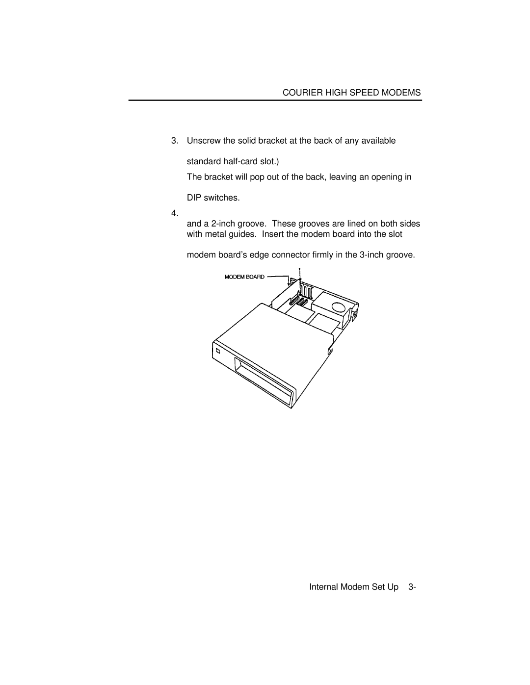
4.
and a
modem board's edge connector firmly in the
Figure 3.3⎯Inserting the Modem
Screw the vertical bracket at the back of the modem firmly to the computer's rear panel, as shown in Figure 3.3. This
and keeps the modem board firmly in place.
6.
Internal Modem Set Up 3-