Chapter 2. Installation
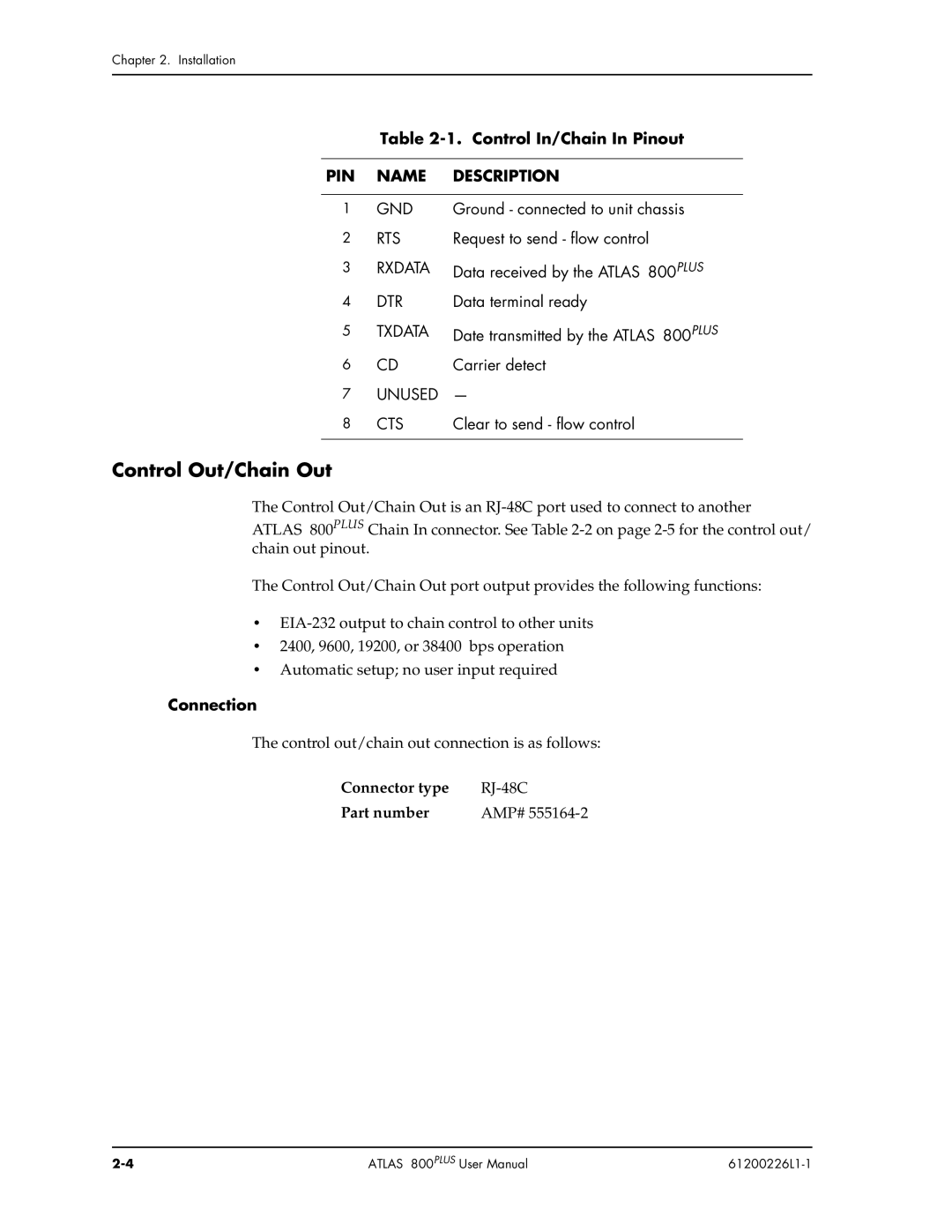
Table 2-1. Control In/Chain In Pinout
PIN | NAME | DESCRIPTION |
|
|
|
1 | GND | Ground - connected to unit chassis |
2 | RTS | Request to send - flow control |
3 | RXDATA | Data received by the ATLAS 800PLUS |
4 | DTR | Data terminal ready |
5 | TXDATA | Date transmitted by the ATLAS 800PLUS |
6 | CD | Carrier detect |
7UNUSED —
8 CTS | Clear to send - flow control |
|
|
Control Out/Chain Out
The Control Out/Chain Out is an
ATLAS 800PLUS Chain In connector. See Table
The Control Out/Chain Out port output provides the following functions:
•
•2400, 9600, 19200, or 38400 bps operation
•Automatic setup; no user input required
Connection
The control out/chain out connection is as follows:
Connector type | |
Part number | AMP# |
ATLAS 800PLUS User Manual |
|