61200226L1-1 ATLAS 800 PLUS User Manual 6-1
Chapter 6 Creating a Dedicated Map

OVERVIEW

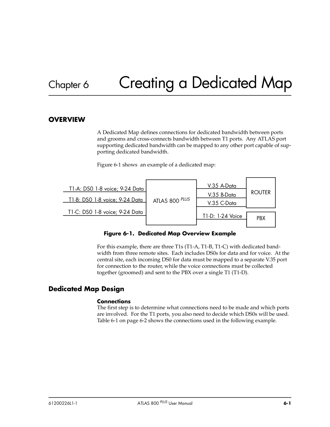
A Dedicated Map defines connections for dedicated bandwidth between ports
and grooms and cross-connects bandwidth between T1 ports. Any ATLAS port
supporting dedicated bandwidth can be mapped to any other port capable of sup-
porting dedicated bandwidth.
Figure 6-1 shows an example of a dedicated map:
Figure 6-1. Dedicated Map Overview Example
For this example, there are three T1s (T1-A, T1-B, T1-C) with dedicated band-
width from three remote sites. Each includes DS0s for data and for voice. At the
central site, each incoming DS0 for data must be mapped to a separate V.35 port
for connection to the router, while the voice connections must be collected
together (groomed) and sent to the PBX over a single T1 (T1-D).

Dedicated Map Design

Connections
The first step is to determine what connections need to be made and which ports
are involved. For the T1 ports, you also need to decide which DS0s will be used.
Table 6-1 on page 6-2 shows the connections used in the following example.
ATLAS 800 PLUS
T1-C: DS0 1-8 voice; 9-24 Data
T1-B: DS0 1-8 voice; 9-24 Data
T1-A: DS0 1-8 voice; 9-24 Data ROUTER
V.35 A-Data
PBX
T1-D: 1-24 Voice
V.35 C-Data
V.35 B-Data